
Furniture combined connecting buckle

A combined connection and buckle technology, which is applied in the direction of thin plate connection, connecting components, mechanical equipment, etc., can solve the problems of inconvenient disassembly and combination, influence on installation, and easy installation errors, etc., so as to improve flexibility and diversification, improve efficiency, reduce The effect of drilling

Active Publication Date: 2019-01-18
淮北创之社信息科技有限公司
View PDF4 Cites 10 Cited by
  • Summary
  • Abstract
  • Description
  • Claims
  • Application Information

AI Technical Summary

Problems solved by technology

[0002] At present, when carrying out furniture installation and combination, it is necessary to drill holes on the boards to facilitate the fixed installation of the connecting components, so that two adjacent boards are fixedly connected. This connection method requires drilling holes on the boards, and in There are requirements on the placement position of the board during assembly, and it is easy to install incorrectly, resulting in damage to the connecting component and affecting the installation. The disassembly and assembly life of the connecting component is limited, and it cannot be combined at will. Hole slots are left, and some furniture needs to be installed and connected by screws when installing, which is time-consuming and laborious, and cannot be combined at will. With the development of personalized furniture, more and more furniture is customized, but after customization, It cannot be adjusted. The existing board connection buckle connects the boards by clamping to realize the connection and fixation of the boards. However, the connection buckle can only connect the boards in two directions. The combined boards have no backboard, which affects the furniture. It needs to be installed with wooden nails later, which affects the installation efficiency and is not easy to disassemble and assemble.

Method used


Image

  • Furniture combined connecting buckle
  • Furniture combined connecting buckle

Examples


Embodiment Construction

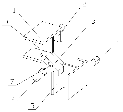
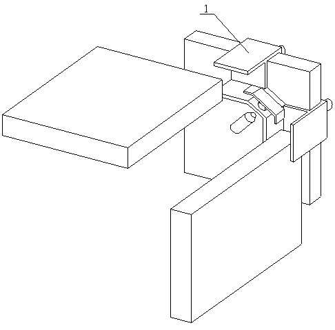
[0032] The combined furniture connection buckle of the present invention is achieved in this way. The combined furniture connection buckle of the present invention includes a corner mounting plate (5), a locking portion and a clamping portion, and the corner mounting plate (5) is composed of The metal plate is bent twice in a row and forms three bending parts. The locking part is placed on the bending part in the middle of the corner mounting plate (5), and the two clamping parts are respectively placed on the corner mounting plate ( 5) On the two outer bending parts;

[0033] The extension lines of the center lines of the two outer bending parts of the corner mounting plate (5) are perpendicular to each other;

[0034] The bending part in the vertical direction of the corner mounting plate (5) is the same length as the bending part in the horizontal direction, and is twice the length of the middle bending part, which can increase the supporting surface for the plate. Less sc...


PUM


Abstract

The invention relates to a furniture combined connecting buckle. According to the connecting buckle, drilling on panels is not needed, dismounting and mounting combination is facilitated, and three panels can be mounted. The efficiency of combined mounting of furniture can be effectively improved. The buckle is characterized in that an angle mounting panel is formed by continuously bending a metalpanel twice, three bending parts are formed, a locking part is arranged on the bending part in the middle of the angle mounting plate, and two clamping parts are arranged on the other two bending parts at the exterior of the angle mounting panel respectively; the extension lines of center lines of the two bending parts at the exterior of the angle mounting panel are perpendicular to each other, the length of the bending part in the vertical direction of the angle mounting plate is the same as that of the bending part in the horizontal part and twice that of the bending part in the middle, a threaded hole is formed in the middle of the angle mounting panel, the locking part is composed of a push plate and a locking screw, and a fastening screw is correspondingly in screw joint in the threaded hole formed in the angle mounting panel.

Description

technical field [0001] The invention relates to a furniture combination connection buckle, which relates to a connection buckle for connecting and fixing plates when furniture is installed and combined, and belongs to the field of furniture processing. In particular, it relates to a connection buckle that does not need to drill holes on the boards, is convenient for disassembly and assembly, and can install three boards. Background technique [0002] At present, when carrying out furniture installation and combination, it is necessary to drill holes on the boards to facilitate the fixed installation of the connecting components, so that two adjacent boards are fixedly connected. This connection method requires drilling holes on the boards, and in There are requirements on the placement position of the board during assembly, and it is easy to install incorrectly, resulting in damage to the connecting component and affecting the installation. The disassembly and assembly life ...

Claims


Application Information

Patent Timeline
Patent Type & Authority Applications(China)
IPC IPC(8): F16B5/02F16B5/06
CPCF16B5/02F16B5/0614
Inventor 不公告发明人
Owner 淮北创之社信息科技有限公司
Learn More