
Dust restraining tank of concrete mixing plant

A mixing station and concrete technology, applied in the field of environmental protection equipment, can solve problems such as high maintenance costs, collapse of dust-proof nets, and considerable environmental pollution, and achieve the effects of alleviating internal air pressure, reducing emission pollution, and improving filtering effects

Inactive Publication Date: 2019-01-18
常德市鼎城盛祥混凝土有限公司
View PDF6 Cites 2 Cited by
  • Summary
  • Abstract
  • Description
  • Claims
  • Application Information

AI Technical Summary

Problems solved by technology

[0002] Concrete is the most commonly used building material in construction engineering. In the concrete mixing of concrete preparation, usually due to the use of sand and gravel aggregates, cement, stone powder or other powder additives, the site is filled with smoke and dust, which is quite polluting to the environment and to workers. The impact on health is bad, especially for the open end of the powder tank, there is usually a lot of smoke and dust, these places are also the main source of smoke pollution, although the existing mixing stations are covered with dust screens on the powder tank, or installed A special vacuum cleaner, but the effect is still not satisfactory, either the dust filter is collapsed, damaged, or clogged, or the installation cost of the vacuum cleaner is too high and the clogging is serious, and the later maintenance cost is extremely high

Method used


Image

  • Dust restraining tank of concrete mixing plant
  • Dust restraining tank of concrete mixing plant
  • Dust restraining tank of concrete mixing plant

Examples


Embodiment Construction

[0025] The implementation of the present invention will be illustrated by specific specific examples below, and those skilled in the art can easily understand other advantages and effects of the present invention from the contents disclosed in this specification.

[0026] Below in conjunction with accompanying drawing and embodiment the present invention will be further described:

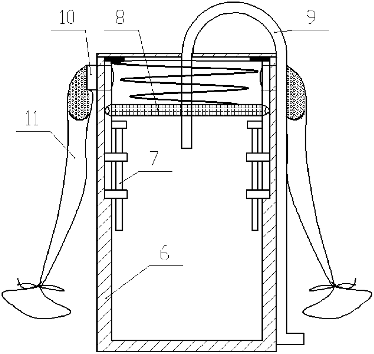
[0027] like figure 1 As shown, a concrete mixing plant dust suppression powder tank includes a cylindrical tank body 6, a feeding pipe 9 is provided on the outside of the tank body 6, the top of the feeding pipe 9 is n-shaped and the outlet end extends into the tank body 6, The top of the tank body 6 is closed, and the outlet end of the feed pipe 9 extends downward into the top of the tank body 6 and passes through the filter plate assembly 8 horizontally arranged in the tank body 6. The filter plate assembly 8 is disc-shaped and has a circumference of A number of balls are arranged on the edge, a...


PUM


Abstract

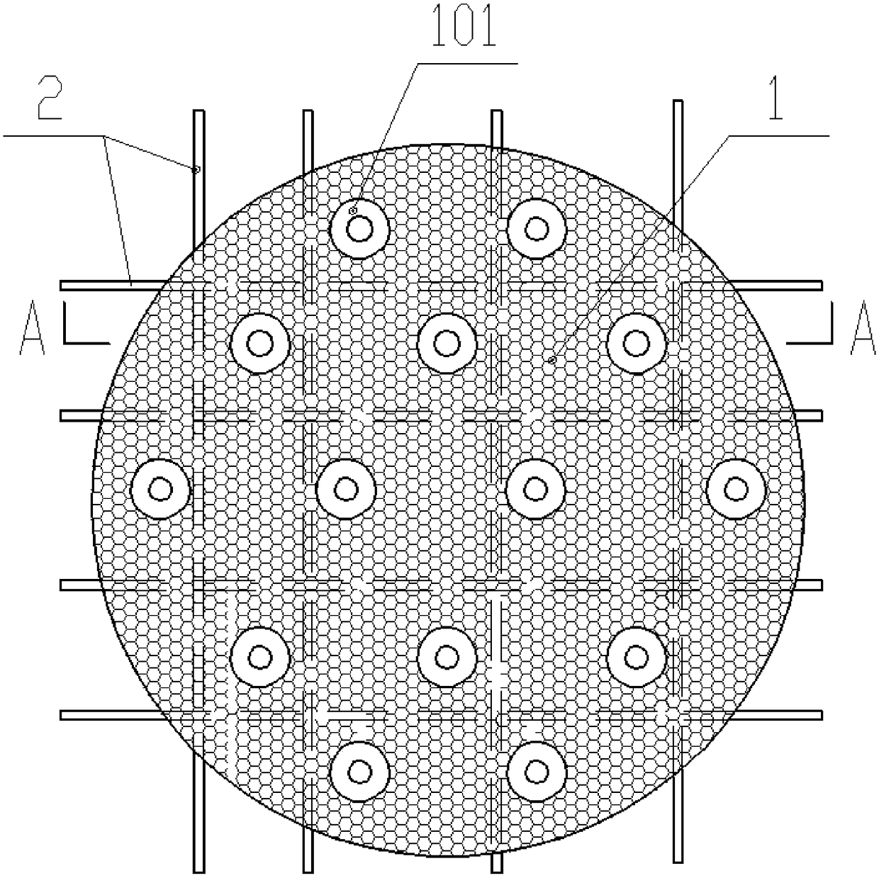
The invention discloses a dust restraining tank of a concrete mixing plant. The top end of a tank body is closed. The outlet end of a feed pipe downwards extends into the top of the tank body and horizontally penetrates through a filtering plate assembly in the tank body. The filtering plate assembly is hung in the tank body through a hanging spring, and the circumferential edge surface of a filtering plate is in sliding fit with the inner wall of the tank body. The top end of the hanging spring is fixed to the inner top wall of the tank body. A plurality of hitting parts are arranged at the position, close to the inner wall of the tank body, of the lower portion of the filtering plate assembly. The filtering plate assembly comprises the filtering plate evenly and fully provided with filtering holes at intervals. The filtering holes run through the upper end face and the lower end face of the filtering plate. Every two adjacent filtering holes are communicated with each other. Concentrated discharge holes perpendicularly running through the upper end face and the lower end face of the filtering plate are formed in the filtering plate and form multiple rows in the filtering plate atintervals. One of injection pipes on the upper layer is arranged between every two adjacent rows of concentrated discharge holes. The dust restraining tank effectively filters out most of particle dust and is safe and free of blockage.

Description

technical field [0001] The invention belongs to the technical field of environmental protection equipment, and in particular relates to a powder tank used for a concrete mixing station on a construction site. Background technique [0002] Concrete is the most commonly used building material in construction engineering. When preparing concrete for concrete mixing, usually due to the use of sand and gravel aggregates, cement, stone powder or other powder additives, the site is full of smoke and dust, which is quite polluting to the environment and to workers. The impact on health is bad, especially for the open end of the powder tank, there is usually a lot of smoke and dust, these places are also the main source of smoke pollution, although the existing mixing stations are covered with dust screens on the powder tank, or installed Specialized vacuum cleaners, but the effect is still unsatisfactory. Either the dust filter is collapsed, damaged, or clogged, or the installation ...

Claims


Application Information

Patent Timeline
IPC IPC(8): B65D88/54B65D90/36B65D88/66B65D90/00
Inventor 张冲
Owner 常德市鼎城盛祥混凝土有限公司
Learn More