
A method for automatic identification of laminated interface when making holes in laminated structure

A technology of automatic identification and laminated structure, applied in automatic control devices, manufacturing tools, boring/drilling and other directions, can solve the problems of increasing the difficulty of axial tool setting, reducing production efficiency, wasting processing time, etc., to simplify the manufacturing process. Hole operation process, improve production efficiency, avoid the effect of empty stroke

Active Publication Date: 2019-10-29
DALIAN UNIV OF TECH
View PDF6 Cites 0 Cited by
  • Summary
  • Abstract
  • Description
  • Claims
  • Application Information

AI Technical Summary

Problems solved by technology

On the one hand, it increases the difficulty of axial tool setting before hole making; on the other hand, in order to ensure that each group of workpiece materials are processed thoroughly, the total stroke of hole making must be increased a little, so that there is a large progress in the processing process. Give empty travel, extra waste of processing time, reduce production efficiency

Method used

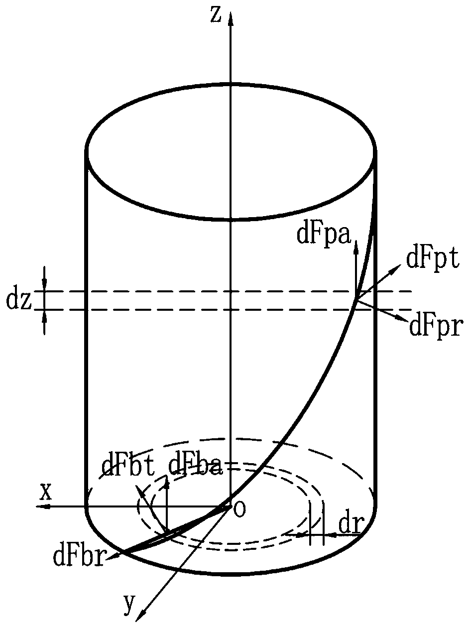
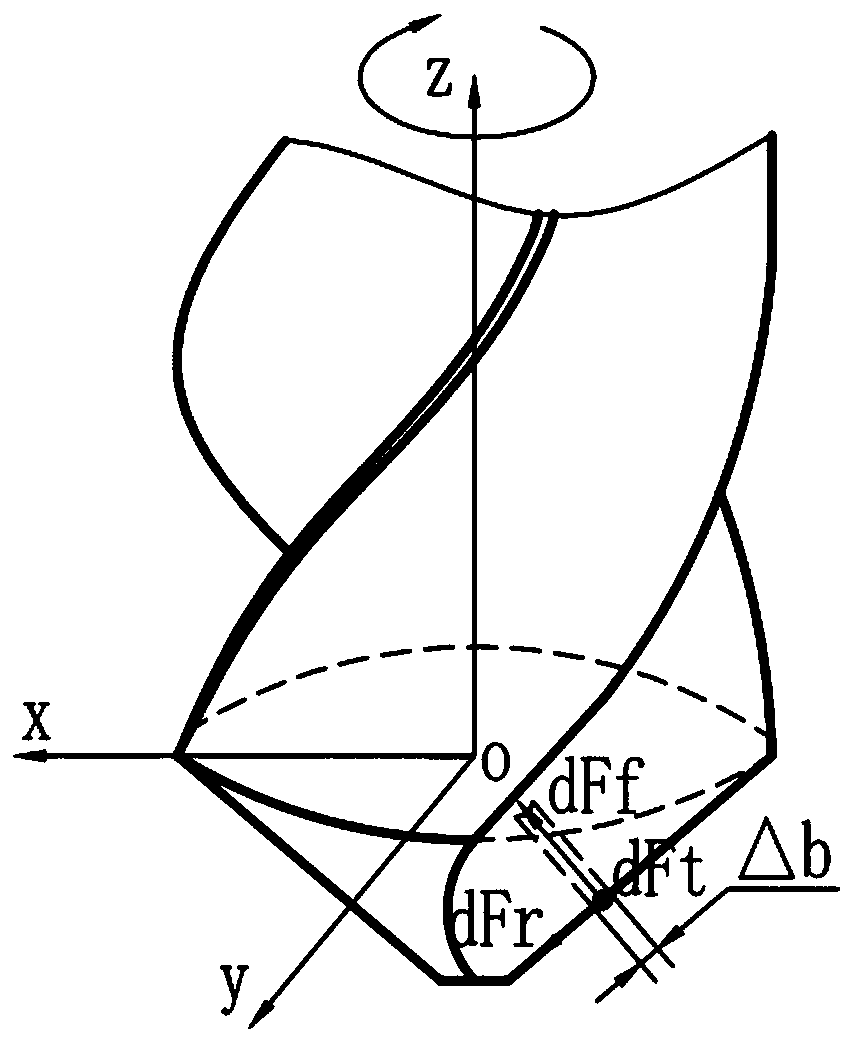

Image

  • A method for automatic identification of laminated interface when making holes in laminated structure
  • A method for automatic identification of laminated interface when making holes in laminated structure
  • A method for automatic identification of laminated interface when making holes in laminated structure

Examples


Embodiment 1

[0042] A method for automatic recognition of the laminated interface when a laminated structure is made a hole. The following uses a portable helical milling unit to process a composite material / titanium alloy laminated structure as an example. The method has the following steps:

[0043] S1. Start the portable helical milling unit to rotate the spindle under no-load. The portable helical milling unit itself integrates an encoder for measuring the spindle speed. Measure and record the no-load speed n of the spindle at this time. 0 ;

[0044] S2. Connect the torque sensor and damper in series on the output end of the main shaft of the portable helical milling unit, start the main shaft of the portable helical milling unit to make it rotate, continuously adjust the damper to change the applied load, and measure the output torque of the main shaft at this time through the torque sensor Accurate value, use the encoder carried by the portable helical milling unit to measure the cor...

Embodiment 2

[0089] A method for automatic recognition of the laminated interface when a laminated structure is hole-making. The following is an example of an ADU drilling composite material / titanium alloy laminated structure. The hole-making tool is a twist drill, and the method has the following steps:

[0090] S1. Start the ADU to make the spindle rotate under no-load. The ADU itself integrates an encoder for measuring the spindle speed. Measure and record the no-load speed n of the spindle at this time. 0 .

[0091] S2. Connect the torque sensor and damper in series at the output end of the ADU main shaft, start the main shaft of the ADU to make it rotate, continuously adjust the damper to change the applied load, measure the accurate value of the output torque of the main shaft at this time through the torque sensor, and use the ADU itself to carry The encoder measures the corresponding spindle speed n under different torques, draws the speed-torque characteristic curve of the ADU spi...


PUM


Abstract

The invention discloses an automatic identification method for a laminated interface during laminated structure drilling. The method has the advantages of measuring and recording an idle rotation speed n0 of a drilling equipment spindle; obtaining a function expression of Td=f(n) of an output torque Td of the drilling equipment spindle with respect to the rotation speed n of the drilling equipmentspindle by experiment and mathematical fitting; deriving a formula of Td=g(n,m,k) for calculating the torque by using the formula; combining two equations to obtain an equation of f(n)=g(n,m,k); determining the corresponding coefficient of mi(i=1,2,3...) for each material, determining other processing parameters except the rotation speed of the drilling equipment spindle, and obtaining the corresponding coefficient ka; solving the rotation speed ni (i = 1, 2, 3...) of the drilling equipment spindle corresponding to different materials; during drilling processing, measuring the real-time rotation speed na of the drilling equipment spindle, comparing na with n0 and ni one by one, and finding a value closest to na, wherein if the value is closest to n0, a cutter does not touch a workpiece orcuts through the workpiece, and if the velue is closest to ni, the drilling equipment processes the workpiece material corresponding to Ni. The method has the advantages of simplifying the drilling operation process, shortening the processing time and the like.

Description

technical field [0001] The invention relates to the technical field of hole-making processing in the assembly of aerospace vehicles, in particular to an automatic identification method for a layer interface when hole-making a layered structure. Background technique [0002] There are a large number of hole-making processing requirements in the assembly process of aerospace vehicles. The workpiece materials during hole making include composite materials, aluminum alloys, titanium alloys, high-strength steels, and different forms of laminated structures composed of two or more materials. Pneumatic processing equipment is widely used in aircraft assembly hole making, including automatic feed drill with pneumatic spindle or air motor, portable helical milling unit, hole making end effector, etc. The characteristic of pneumatic tools is that the spindle speed cannot be precisely controlled, and the spindle speed changes with the external load. These processing equipment lack th...

Claims


Application Information

Patent Timeline
Patent Type & Authority Patents(China)
IPC IPC(8): B23Q15/00B23B35/00
CPCB23B35/00B23B41/00B23C3/00
Inventor 董志刚康仁科杨国林严超朱祥龙
Owner DALIAN UNIV OF TECH
Learn More