
Punching mold for permanent magnet motor rotor

A technology of rotor punching and permanent magnet motors, which is applied in the manufacture of motor generators, stator/rotor bodies, electrical components, etc., can solve the problems of long manufacturing cycle and cost at least hundreds of thousands of yuan, and achieve positioning High precision, improve product processing efficiency, and ensure the effect of punching product quality

Inactive Publication Date: 2019-01-18
大连电机集团有限公司
View PDF6 Cites 3 Cited by
  • Summary
  • Abstract
  • Description
  • Claims
  • Application Information

AI Technical Summary

Problems solved by technology

However, the cost of a set of high-precision progressive dies is at least hundreds of thousands of yuan.
And the manufacturing cycle is relatively long. In summary, the above-mentioned solutions are not suitable for trial production of prototypes of this type of punching

Method used


Image

  • Punching mold for permanent magnet motor rotor
  • Punching mold for permanent magnet motor rotor
  • Punching mold for permanent magnet motor rotor

Examples


Embodiment Construction

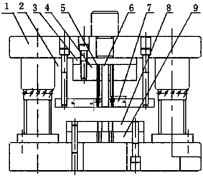
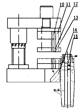
[0029] The present invention will be described in detail below in conjunction with the accompanying drawings. This set of molds is processed in strict accordance with the requirements of the drawings, and according to the stamping process when stamping. The stamped pieces achieve the expected effect.

[0030] like Figure 1-3 As shown, the permanent magnet motor rotor punching single punching die includes a mold base 1, an upper die backing plate 3, a punch fixing plate 4, a flux leakage hole punch 5, a small magnetic steel groove punch 6, a lower die 8, a lower die Die base 16, lower die backing plate 9, large magnetic steel groove punch 10, weight reduction hole punch 11, small flux leakage hole punch 12, large flux leakage hole punch 13, center positioning shaft 14; Two gap-free rolling guide columns are connected to the upper and lower mold bases, the center of the lower end surface of the mold base 1 is provided with an upper mold backing plate 3, the lower end of the up...


PUM

PropertyMeasurementUnit
diameteraaaaaaaaaa
thicknessaaaaaaaaaa

Abstract

The invention relates to a punching mold for a permanent magnet motor rotor. The punching mold for the permanent magnet motor rotor comprises a mold rack, an upper mold pad plate, a punch fixing plate, a magnetic leakage hole punch, a small magnetic steel groove punch, a lower mold body, a lower mold base, a lower mold pad plate, a large magnetic steel groove punch, a weight decrease hole punch, asmall magnetic leakage hole punch, a large magnetic leakage hole punch and center positioning shafts; the mold rack is formed by connecting two non-gap rolling guide columns, the upper mold pad plateis arranged in the center of the lower end face of the mold rack, the punch fixing plate is arranged at the lower end of the upper mold pad plate, and the upper mold pad plate and the punch fixing plate are fixed to the mold rack through bolts; multiple punches are fixed to the punch fixing plate; stripping plates are arranged at the lower ends of the punches, the lower mold pad plate is arrangedbelow the lower mold body, and the center positioning shafts are arranged on the side faces of the centers of the lower mold body, the lower mold pad plate and the lower mold base. The processed rotor punching product is high in positioning precision and cooperates with the center positioning shafts, the center positioning shafts can achieve accurate positioning, the quality of punching productsis guaranteed, and the processing efficiency of products is improved.

Description

technical field [0001] The invention relates to a single punch die for punching a rotor of a permanent magnet motor, which is applied in the production industry of high-efficiency and light-weight permanent magnet motor iron cores for vehicles. Background technique [0002] The characteristics of the single-slot punching die are generally used in trial production of new products, or small batches of motor stator and rotor punches with relatively simple slot shapes. [0003] The permanent magnet motor rotor punching sheet is usually composed of small magnetic steel holes, large magnetic steel holes, large magnetic flux leakage holes, magnetic flux leakage holes, small magnetic flux leakage holes, weight reduction holes and shaft holes. The material used is 0.3mm thick silicon steel plate . Such a complex rotor with so many special-shaped holes is generally cut by wire cutting or laser cutting if you want to make a trial production of a new product. This processing technology...

Claims


Application Information

Patent Timeline
Patent Type & Authority Applications(China)
IPC IPC(8): B21D28/14B21D28/22H02K15/03
CPCB21D28/14B21D28/22H02K15/03
Inventor 孙永晶毛永光岳军董修全
Owner 大连电机集团有限公司
Learn More