
Camera mechanism and mobile terminal

A mobile terminal and camera technology, applied in the direction of image communication, TV, color TV parts, etc., can solve the problem that the shooting angle is not easy to expand, and achieve the effect of simple structure, large shooting angle, and easy realization

Inactive Publication Date: 2019-01-15
NUBIA TECHNOLOGY CO LTD
View PDF5 Cites 2 Cited by
  • Summary
  • Abstract
  • Description
  • Claims
  • Application Information

AI Technical Summary

Problems solved by technology

[0004] The main purpose of the present invention is to provide a camera mechanism and a mobile terminal, which aims to solve the problem that the shooting angle of view of the mobile terminal is not easy to expand in the prior art

Method used


Image

  • Camera mechanism and mobile terminal
  • Camera mechanism and mobile terminal
  • Camera mechanism and mobile terminal

Examples


Embodiment Construction

[0027] It should be understood that the specific embodiments described here are only used to explain the present invention, not to limit the present invention.

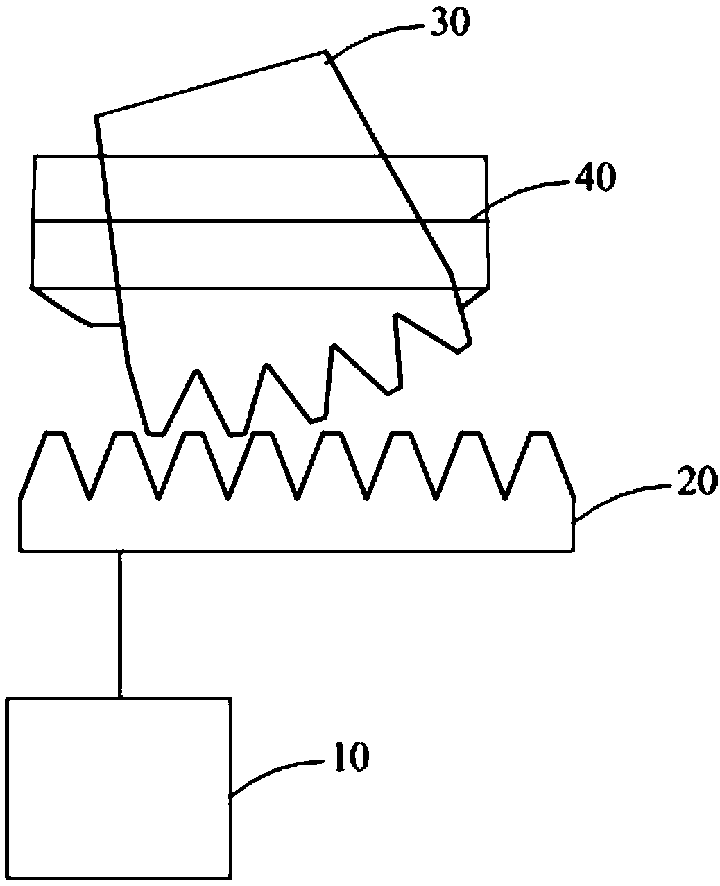
[0028] Such as Figure 1-2 as shown, figure 1 It is a structural schematic diagram of the camera mechanism of the present invention; figure 2 It is a structural schematic diagram of the horizontal movement of the gear assembly driven by the motor in the camera mechanism of the present invention.

[0029] refer to figure 1 , figure 1 It is a structural schematic diagram of the camera mechanism of the present invention.

[0030] The present invention provides a camera mechanism, which is applied to a mobile terminal 50. The camera mechanism includes a motor 10, a gear assembly 20, and a camera module 30. The bottom of the camera module 30 is provided with a passive gear 301 matched with the gear assembly 20;

[0031] The motor 10 is connected to the gear assembly 20; the gear assembly 20 is meshed with the driven ...


PUM


Abstract

The invention discloses a camera mechanism and a mobile terminal, wherein, the camera mechanism comprises a motor, a gear assembly and a camera module; the bottom of the camera module is provided witha passive gear adapted to the gear assembly; The motor is connected with the gear assembly; The gear assembly is meshed and connected with the passive gear; When the mobile terminal receives the ultra wide angle shooting instruction, the motor is driven to drive the gear assembly to move horizontally so as to drive the camera module to rotate. The passive gear is arranged at the bottom of the camera module, and the rotation of the camera module is effectively realized through the cooperation of a motor and a gear assembly, and the structure is simple and easy to realize. Moreover, the shooting mode of the mobile terminal can be set with a super wide angle shooting mode, and when the super wide angle shooting mode is triggered, the motor is started, so that the camera module is driven to rotate, and a larger shooting angle is obtained without moving the mobile terminal or moving the mobile terminal in a small range.

Description

technical field [0001] The invention relates to the technical field of mobile terminals, in particular to a camera mechanism and a mobile terminal. Background technique [0002] In recent years, the development of smart phones has brought more and more convenience and experience to users' daily life, and has become a necessity of life. At the same time, users have more and more diverse functional requirements for smart phones. In order to obtain a larger shooting angle, various mobile phone manufacturers have developed cameras that can rotate. [0003] However, the rotatable camera of the existing mobile phone is usually manually rotated, which is inconvenient to operate. It only changes the shooting angle of the camera, but cannot shoot during the rotation, or the structure of the rotation is relatively complicated. Contents of the invention [0004] The main purpose of the present invention is to provide a camera mechanism and a mobile terminal, aiming at solving the pr...

Claims


Application Information

Patent Timeline
Patent Type & Authority Applications(China)
IPC IPC(8): H04N5/225
CPCH04N23/45H04N23/50H04N23/57
Inventor 余遥琴
Owner NUBIA TECHNOLOGY CO LTD
Learn More