
A plastic skeleton structure with pins for inductive coils

A technology of inductance coil and plastic skeleton, applied in the field of inductors, can solve the problems of pin drop, instability, and the influence of production qualification rate, and achieve the effect of increasing plugging force and improving heat dissipation.

Active Publication Date: 2019-01-15
WUXI JINGLEI ELECTRONICS
View PDF5 Cites 2 Cited by
  • Summary
  • Abstract
  • Description
  • Claims
  • Application Information

AI Technical Summary

Problems solved by technology

The pins are horizontally bitten to ensure the connection strength between the pins and the frame. Generally, the insertion force is about 3Kg. However, when the pins and frame are under high temperature, the insertion force of the frame hole drops rapidly in a short moment, and is affected by the heated air in the pinhole. , the pins are pushed out, causing the pins to be pulled out, and in severe cases, the pins will fall off. This instability has a serious impact on the coil process production and the coil production qualification rate, and the plastic material can only guarantee the electrical insulation of the coil skeleton, but cannot guarantee The body conducts heat, therefore, a plastic skeleton structure with pins for the inductance coil is proposed to solve the above problems

Method used


Image

  • A plastic skeleton structure with pins for inductive coils
  • A plastic skeleton structure with pins for inductive coils
  • A plastic skeleton structure with pins for inductive coils

Examples


Embodiment Construction

[0024] The following will clearly and completely describe the technical solutions in the embodiments of the present invention with reference to the accompanying drawings in the embodiments of the present invention. Obviously, the described embodiments are only some, not all, embodiments of the present invention. Based on the embodiments of the present invention, all other embodiments obtained by persons of ordinary skill in the art without making creative efforts belong to the protection scope of the present invention.

[0025] see Figure 1-7 , the present invention provides a technical solution:

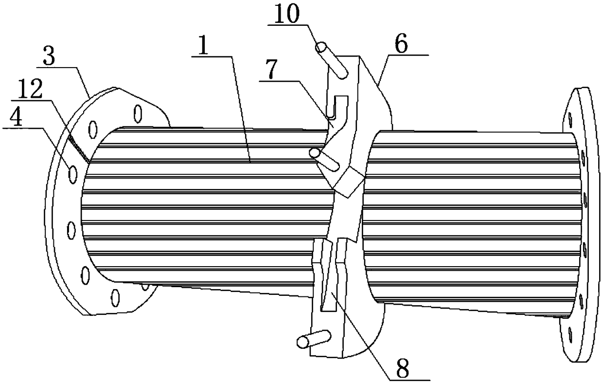
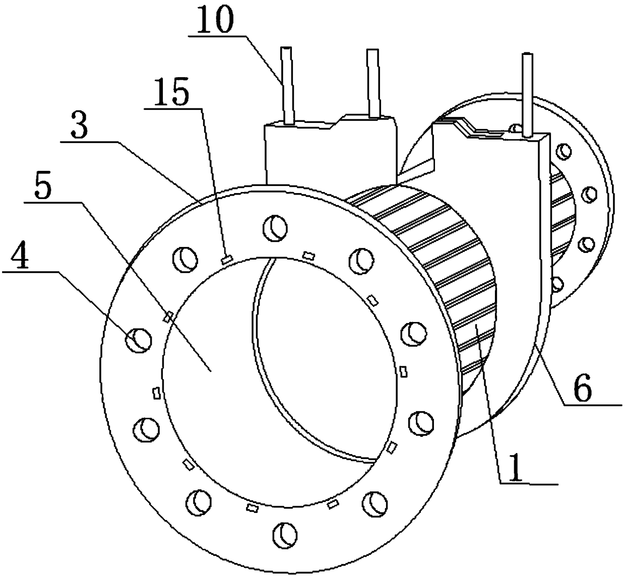
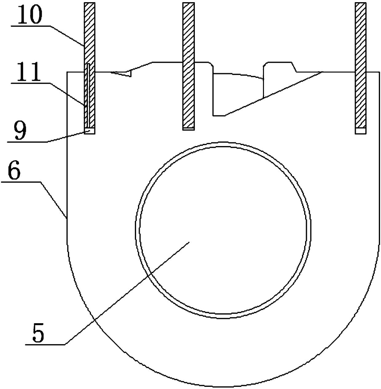
[0026] A plastic skeleton structure with stitches for an inductance coil, including a winding core 1, a heat dissipation groove 2, a baffle plate 3, a heat dissipation hole a4, a partition plate 6, a stitch 10, a round hole 13 and a heat dissipation hole b15, the winding core 1 is provided with a plurality of cooling grooves 2 in the horizontal direction, and a through hole 5 is p...


PUM


Abstract

The invention relates to the technical field of inductors, in particular to a plastic skeleton structure with pins for inductive coils. Through the vertical exhaust groove arranged at the lower end ofthe pin, As that pin is insert, no positive pressure is formed in the air in the pin hole, As that gas in the pinhole enter with the pin, Gas escapes from the vertical exhaust slot, there is no positive pressure gas in the hole, so that that insertion and extraction force is increase, At that same time, the high-temperature gas doe not run out along the vertical exhaust slot when soldering the tin instantaneously, avoiding the risk of pins being pushed out, through the heat dissipation groove and the heat dissipation hole, and the heat dissipation hole is communicated with the heat dissipation groove, As that coil is wound around the core, A heat dissipation hole (a) is arranged so as to better dissipate heat for the coil in operation. A partition plate is sleeved on the core, and a clipblock on the partition plate is stuck in the heat dissipation groove, so that the partition plate can be moved around the core again to meet different use requirements.

Description

technical field [0001] The invention relates to the technical field of inductors, in particular to a plastic frame structure with pins for an inductor coil. Background technique [0002] The inductance coil is an electromagnetic induction element wound with insulated wires. It is generally composed of a skeleton, a winding, a shield, a packaging material, a magnetic core, etc. Some larger fixed inductors or adjustable inductors are mostly surrounded by enameled wires. On the skeleton, the magnetic core is put into the inner cavity of the skeleton to increase its inductance. Therefore, there is an increasing demand for a plastic skeleton structure with pins for the inductance coil. [0003] The plastic frame is usually used to wind the coil, and is connected by high-temperature tin furnace immersion soldering. The connection strength between the pin and the frame is required to be relatively high, and it is required not to fall off at a high temperature above 420 degrees. At ...

Claims


Application Information

Patent Timeline
Patent Type & Authority Applications(China)
IPC IPC(8): H01F27/29H01F27/30H01F27/28
Inventor 杨正义
Owner WUXI JINGLEI ELECTRONICS
Learn More