
Automatic identification method and device of electrical-imaging logging facies

An automatic identification and imaging logging technology, which is applied in measurement devices, scene identification, neural learning methods, etc., can solve the problems of low identification accuracy, low application range and identification accuracy, and achieve good research and prediction, good processing efficiency and high accuracy. The effect of recognition accuracy

Active Publication Date: 2019-01-15
PETROCHINA CO LTD
View PDF6 Cites 9 Cited by
  • Summary
  • Abstract
  • Description
  • Claims
  • Application Information

AI Technical Summary

Problems solved by technology

[0003] There are two main methods for the existing electrical imaging logging facies automatic recognition technology. One is to identify and quantitatively extract various geological features in the image based on the image segmentation of the imaging logging image, and then according to different geological feature phenomena and The relationship between logging facies is classified and identified by methods such as fuzzy mathematics and neural network. This method is controlled by the image segmentation quality and geological feature recognition effect, and the recognition accuracy is low; another method is to select typical images of different logging facies The logging image is used as a template, and the characteristic parameter curves of typical images of various logging facies are counted, and the template with the highest similarity determined by correlation matching and other methods for the image of the well section to be identified is considered to be the corresponding logging facies category. Influenced by the selected characteristic parameters, the scope of application and identification accuracy are low, which cannot meet the needs of geological research and reservoir evaluation

Method used


Image

  • Automatic identification method and device of electrical-imaging logging facies
  • Automatic identification method and device of electrical-imaging logging facies
  • Automatic identification method and device of electrical-imaging logging facies

Examples


Embodiment Construction

[0028] The following will clearly and completely describe the technical solutions in the embodiments of the present invention with reference to the accompanying drawings in the embodiments of the present invention. Obviously, the described embodiments are only some of the embodiments of the present invention, not all of them. Based on the embodiments of the present invention, all other embodiments obtained by persons of ordinary skill in the art without making creative efforts belong to the protection scope of the present invention.

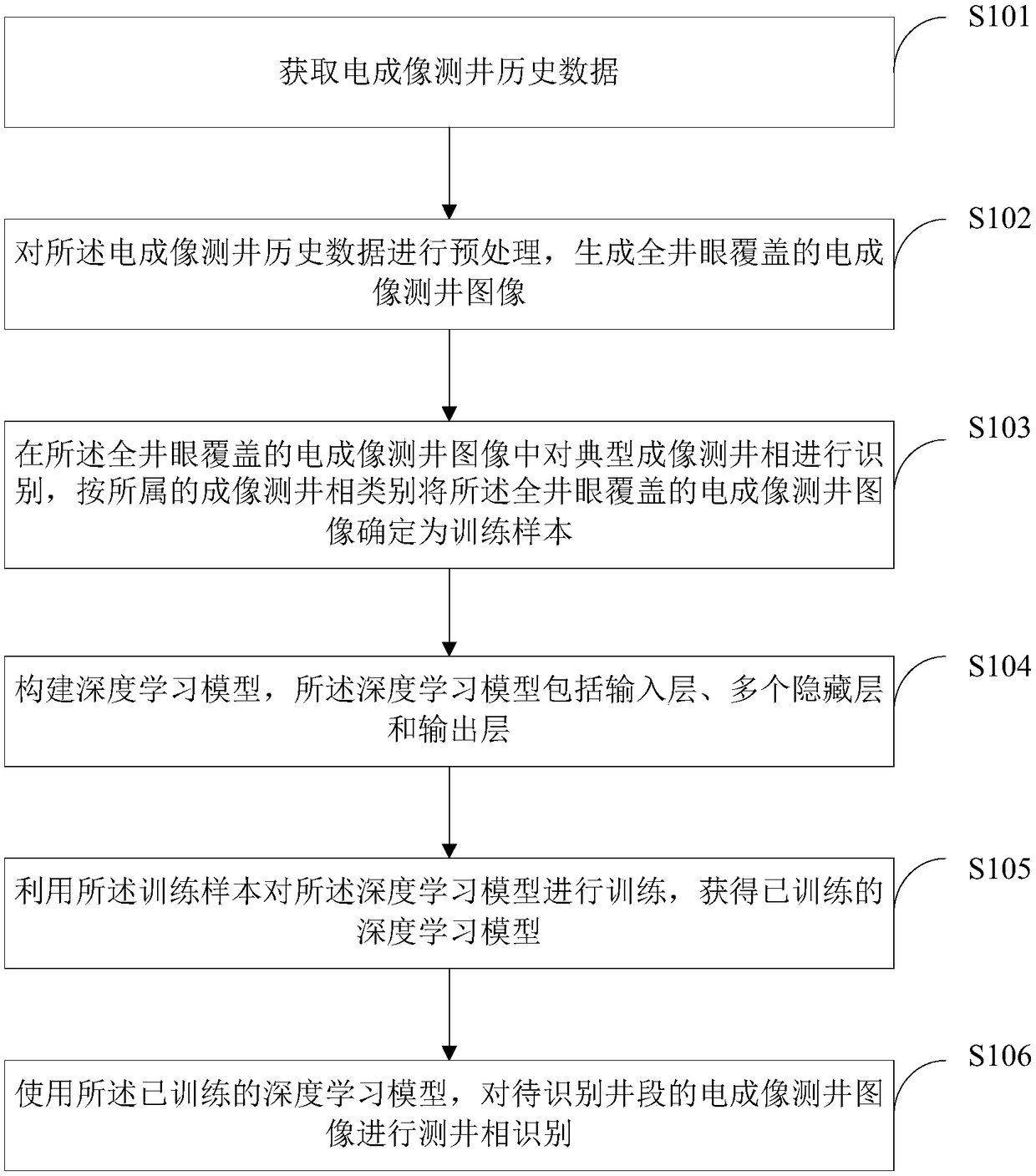
[0029] In an embodiment of the present invention, a method for automatic identification of electrical imaging logging facies is provided, such as figure 1 As shown, the method includes:

[0030] S101: Obtain historical electrical imaging logging data;

[0031] S102: Preprocessing the electrical imaging logging historical data to generate an electrical imaging logging image covering the entire borehole;

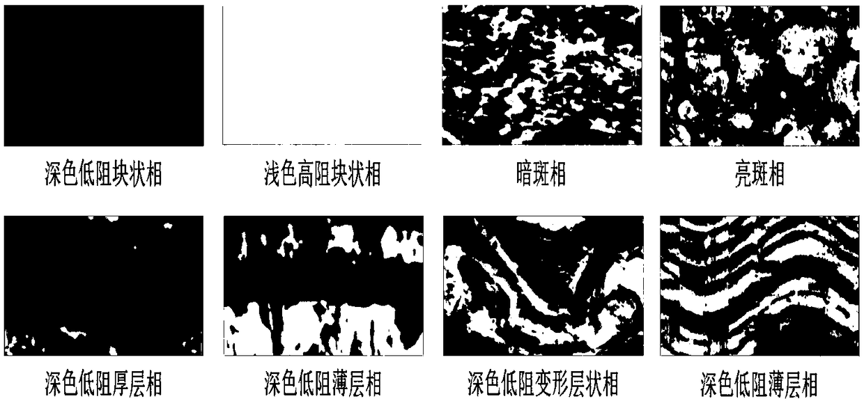
[0032] S103: Identify typical imaging lo...


PUM


Abstract

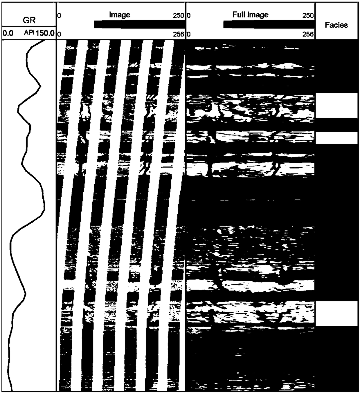
The invention provides an automatic identification method and device of an electrical-imaging logging facies. The method includes: acquiring electrical-imaging logging history data; pre-processing theelectrical-imaging logging history data, and generating electrical-imaging logging images of full borehole coverage; identifying typical imaging logging facies in the electrical-imaging logging images of full borehole coverage, and determining the the electrical-imaging logging images of full borehole coverage as training samples according to imaging logging facies classes to which the same belong; constructing a deep learning model, wherein the deep learning model includes an input layer, a plurality of hidden layers and an output layer; using the training samples to train the deep learningmodel to obtain a trained deep learning model; and using the trained deep learning model for logging facies identification on an electrical-imaging logging image of a to-be-identified well segment. According to the scheme, imaging logging facies types of all segments can be automatically and accurately identified, and thus distribution laws of reservoirs can be better studied and predicted.

Description

technical field [0001] The invention relates to the technical field of electrical imaging logging data processing and interpretation, in particular to a method and device for automatic identification of electrical imaging logging facies. Background technique [0002] Electrical imaging logging facies refers to the color, structure and other characteristics of different types of sedimentary strata on electrical imaging logging images. By analyzing electrical imaging logging facies and establishing relationships with stratum lithofacies and sedimentary facies, reservoir It provides an important basis for the comprehensive evaluation of layer logging and the prediction of high-quality reservoir distribution. Traditional electronic imaging logging facies interpretation mainly requires experts to directly divide the images based on experience, which is highly subjective and difficult to meet the urgent needs of oilfield production. How to automatically identify electrical imagin...

Claims


Application Information

Patent Timeline
IPC IPC(8): G01V3/18G01V3/38G06V10/82
CPCG01V3/18G01V3/38G06N3/084G06N3/082G06V10/454G06V10/82G06N3/048G06N3/045G06N3/08G06N3/04G01V3/20G06F18/214
Inventor 冯周武宏亮李宁王克文刘鹏李雨生王华峰徐彬森
Owner PETROCHINA CO LTD
Learn More