Heat cycling device

A thermal cycle device, work space technology, used in waste heat treatment, lighting and heating equipment, furnace components, etc., can solve problems such as unutilized energy

Inactive Publication Date: 2019-01-15
兰溪市代丰网络科技有限公司
View PDF0 Cites 3 Cited by
  • Summary
  • Abstract
  • Description
  • Claims
  • Application Information

AI Technical Summary

Problems solved by technology

However, the existing smelting equipment discharges this part of high-heat exhaust gas directly or after purification, and does not use the energy contained in it.

Method used


Image

  • Heat cycling device
  • Heat cycling device
  • Heat cycling device

Examples


Embodiment Construction

[0013] The following will clearly and completely describe the technical solutions in the embodiments of the present invention with reference to the accompanying drawings in the embodiments of the present invention. Obviously, the described embodiments are only some, not all, embodiments of the present invention. Based on the embodiments of the present invention, all other embodiments obtained by persons of ordinary skill in the art without making creative efforts belong to the protection scope of the present invention.

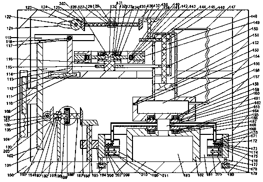
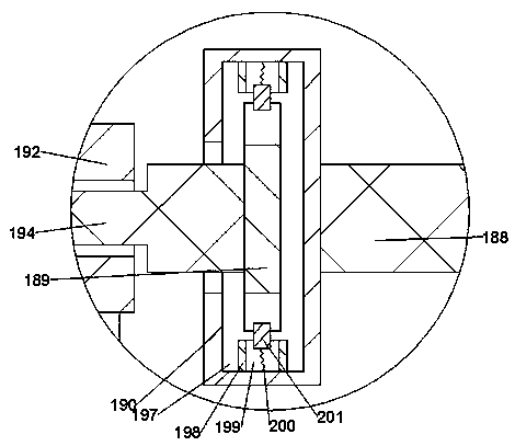
[0014] see Figure 1-3 , an embodiment provided by the present invention: a heat cycle device, including a working box 100, a working space 101 is arranged in the working box 100, a speed regulating space 114 is arranged in the upper end wall of the working space 101, and the working space The lower end wall of 101 is fixedly connected with a working furnace 182. The working furnace 182 is symmetrically provided with a cooling mechanism 180. The outer side of ...


PUM


Abstract

The invention discloses a heat cycling device, which comprises a work box, wherein a work space is formed in the work box, a speed regulating space is formed in the upper end wall of the work space, aworking furnace is fixedly connected with the lower end wall of the work space, the left and right sides of the working furnace are symmetrically provided with cooling mechanisms, a ring-shaped blockis arranged on the outer side of the working furnace, a cooling space with upper and lower end walls communicated with the work space is formed in the ring-shaped block, the cooling mechanisms are fixedly connected with the left and right end walls of the cooling space, and a ring-shaped groove with the upper end wall communicated with the work space is formed in the lower end wall of the work space. The heat cycling device has the advantages of simple structure and convenient operation, can utilize the high-temperature exhaust gas generated by iron smelting or other processes to perform cooling control on a refining furnace, ensures the normal progress of refining, performs more powerful control when the refining temperature is too high, can ensure stable and even cooling, make full useof the energy generated by the exhaust gas, and saves a lot of resources.

Description

technical field [0001] The invention relates to the field of waste gas utilization, in particular to a thermal cycle device. Background technique [0002] During the smelting process of steel or other metals, a large amount of high-heat exhaust gas will be produced, and the smelting of steel needs to control the temperature so that the quality of the output products can be controlled. However, the existing smelting equipment discharges this part of high-heat exhaust gas directly or after purification, and does not utilize the energy contained in it. Contents of the invention [0003] The object of the present invention is to provide a thermal cycler to solve the problems raised in the background art above. [0004] In order to achieve the above object, the present invention provides the following technical solutions: thermal cycle device, including a working box, a working space is arranged in the working box, a speed regulating space is arranged in the upper end wall of ...

Claims


Application Information

Patent Timeline
Patent Type & Authority Applications(China)
IPC IPC(8): F27D17/00
CPCF27D17/004F27D2017/006Y02P10/25
Inventor 殷浩
Owner 兰溪市代丰网络科技有限公司
Why Eureka
Try Eureka