
High-temperature flue gas purification treatment device for biomass boiler

A biomass boiler and high-temperature flue gas technology, applied in the direction of reducing greenhouse gases, climate sustainability, fixed tubular conduit components, etc., can solve the problems of large boiler energy consumption, large heat loss, and temperature rise

Inactive Publication Date: 2019-01-15
曾金玉
View PDF5 Cites 4 Cited by
  • Summary
  • Abstract
  • Description
  • Claims
  • Application Information

AI Technical Summary

Problems solved by technology

[0003] The purpose of the present invention is to provide a biomass boiler high-temperature flue gas purification treatment device in order to solve the above problems, which solves the problem that the high-temperature flue gas generated during the use of the existing biomass boiler is directly discharged into the air, and the heat of the high-temperature flue gas Not only does it lead to an increase in the ambient temperature of the air, but also a large loss of heat energy. New low-temperature fuel and air enter the boiler to absorb the heat inside the boiler, resulting in high energy consumption and high cost of the boiler, and the harmful substances contained in the flue gas will be reduced. Damage to the environment and poor practicality

Method used


Image

  • High-temperature flue gas purification treatment device for biomass boiler
  • High-temperature flue gas purification treatment device for biomass boiler
  • High-temperature flue gas purification treatment device for biomass boiler

Examples


Embodiment Construction

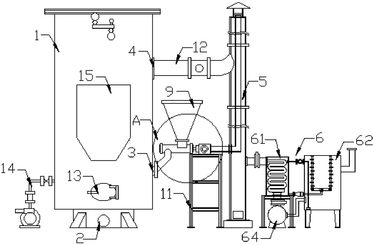
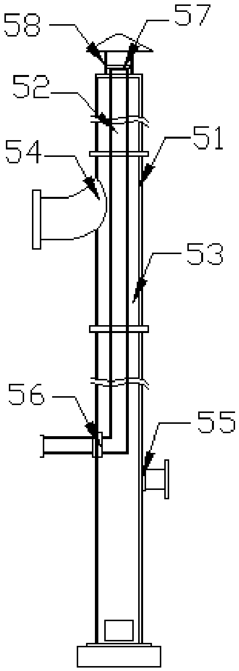
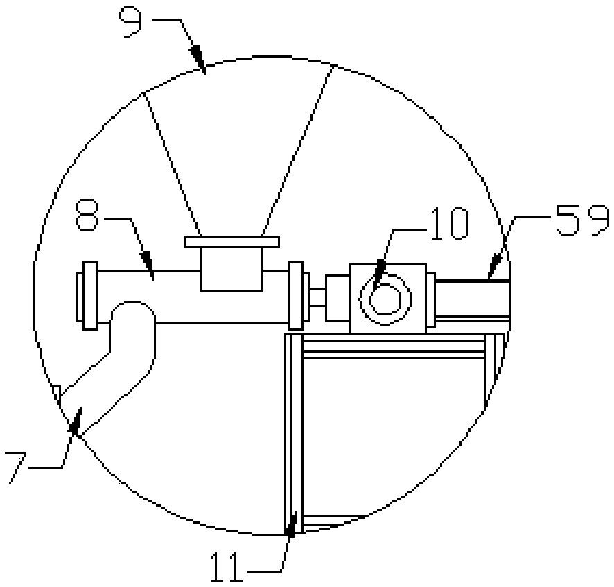
[0021] Such as Figure 1-4 As shown, this specific embodiment adopts the following technical solutions: a biomass boiler high-temperature flue gas purification treatment device, including a biomass combustion boiler 1, a biomass fuel inlet 3, a flue gas outlet 4, a first waste heat utilization device 5, Flue gas treatment device 6, feed pipe 7, feed channel 8, feed hopper 9, blower 10, frame 11, high temperature flue gas pipeline 12 and burner 13, the biomass combustion boiler 1, the biomass A base 2 is fixedly installed on the bottom of the combustion boiler 1, a burner 13 is installed inside the biomass combustion boiler 1, and a biomass fuel inlet 3 is opened on the biomass combustion boiler 1 on one side of the burner 13, and the biomass fuel inlet 3 is provided on the biomass combustion boiler 1 side. A flue gas outlet 4 is provided on the biomass combustion boiler 1 at the top of the biomass fuel inlet 3, and the output end of the flue gas outlet 4 communicates with one ...


PUM


Abstract

The invention discloses a high-temperature flue gas purification treatment device for a biomass boiler. The high-temperature flue gas purification treatment device comprises a biomass combustion boiler, a biomass fuel inlet, a flue gas outlet, a first waste heat utilization device, a flue gas treatment device, a guiding pipe, a feeding channel, a feeding hopper, an air blower, a rack, a high-temperature flue gas pipeline and a combustor; and a base is fixedly mounted at the bottom of the biomass combustion boiler, the combustor is mounted in the biomass combustion boiler, and the biomass fuelinlet is formed in the position, on one side of the combustor, of the biomass combustion boiler. The high-temperature flue gas purification treatment device is simple in structure, convenient to use,and capable of achieving energy saving and environment protection ; and preheating treatment of biomass fuel and air required by combustion is achieved, energy consumption and the cost of boiler combustion are lowered, the absorption efficiency of harmful substances can be improved through heated water, the flue gas purification effect is ensured, pollution of the biomass combustion boiler on theenvironment is lowered, the utilization rate of boiler flue gas thermal energy is increased, and practicality is higher.

Description

Technical field: [0001] The invention relates to the technical field of biomass boilers, in particular to a biomass boiler high-temperature flue gas purification treatment device. Background technique: [0002] Boilers that use biomass energy as fuel are called biomass boilers. The efficiency of biomass boilers is generally above 80%. The larger the boiler model, the more fully the combustion, the higher the efficiency of the boiler, the highest reaching 88.3%. 15% higher than the average efficiency level of coal-fired boilers. However, the high-temperature flue gas generated when the existing biomass boiler is in use is directly discharged into the air. The heat of the high-temperature flue gas not only causes the temperature of the air environment to rise, but also causes a large loss of heat energy. New lower-temperature fuel and air enter the boiler for absorption. The heat inside the boiler results in high energy consumption and high cost, and the harmful substances co...

Claims


Application Information

Patent Timeline
IPC IPC(8): F23J15/06F28D7/08F23J15/04
CPCF23J15/04F23J15/06F28D7/08Y02E20/30
Inventor 曾金玉
Owner 曾金玉
Learn More