
Intra-die self-locking mechanism of plastic die

A plastic mold and self-locking technology, applied in the field of plastic molds, can solve the problems of inability to effectively prevent the mechanism from returning, increase the cost of mold use, reduce the service life of the oil cylinder, etc., to ensure the processing accuracy and appearance requirements of the product, and increase the service life. , the effect of reducing the size of the cylinder

Inactive Publication Date: 2019-01-15
伊构尔实业(苏州)有限公司
View PDF4 Cites 1 Cited by
  • Summary
  • Abstract
  • Description
  • Claims
  • Application Information

AI Technical Summary

Problems solved by technology

In order to overcome the expansion and opening force of the melt in the cavity to the mold during injection, the locking force applied to the mold by the injection machine will generate a force to support the mold when the raw material is injected into the cavity at high pressure, so the clamping unit of the injection molding machine must be Provide enough "clamping force" to prevent the mold from being stretched. In order to provide enough "clamping force" to prevent the front mold insert from retreating under the clamping pressure, the existing method usually increases the oil cylinder. Bore, use of self-locking cylinders, etc., the use of large-bore cylinders means that the cylinders with greater thrust will increase with the increase of the bore, and the price of the cylinder will also increase, which will increase the cost of the mold. The problem of oil leakage after the lock oil cylinder is used for a long time will reduce the service life of the oil cylinder, which also increases the cost of use, and cannot effectively prevent the mechanism from retreating

Method used


Image

  • Intra-die self-locking mechanism of plastic die
  • Intra-die self-locking mechanism of plastic die
  • Intra-die self-locking mechanism of plastic die

Examples


Embodiment Construction

[0017] It should be noted that when an element is referred to as being “fixed” to another element, it can be directly on the other element or there can also be an intervening element. When an element is referred to as being "connected to" another element, it can be directly connected to the other element or intervening elements may also be present.

[0018] Unless otherwise defined, all technical and scientific terms used herein have the same meaning as commonly understood by one of ordinary skill in the technical field of the invention. The terms used herein in the description of the present invention are for the purpose of describing specific embodiments only, and are not intended to limit the present invention. As used herein, the term "and / or" includes any and all combinations of one or more of the associated listed items.

[0019] In order to make the purpose, technical solutions and advantages of the embodiments of the present invention clearer, the technical solutions ...


PUM


Abstract

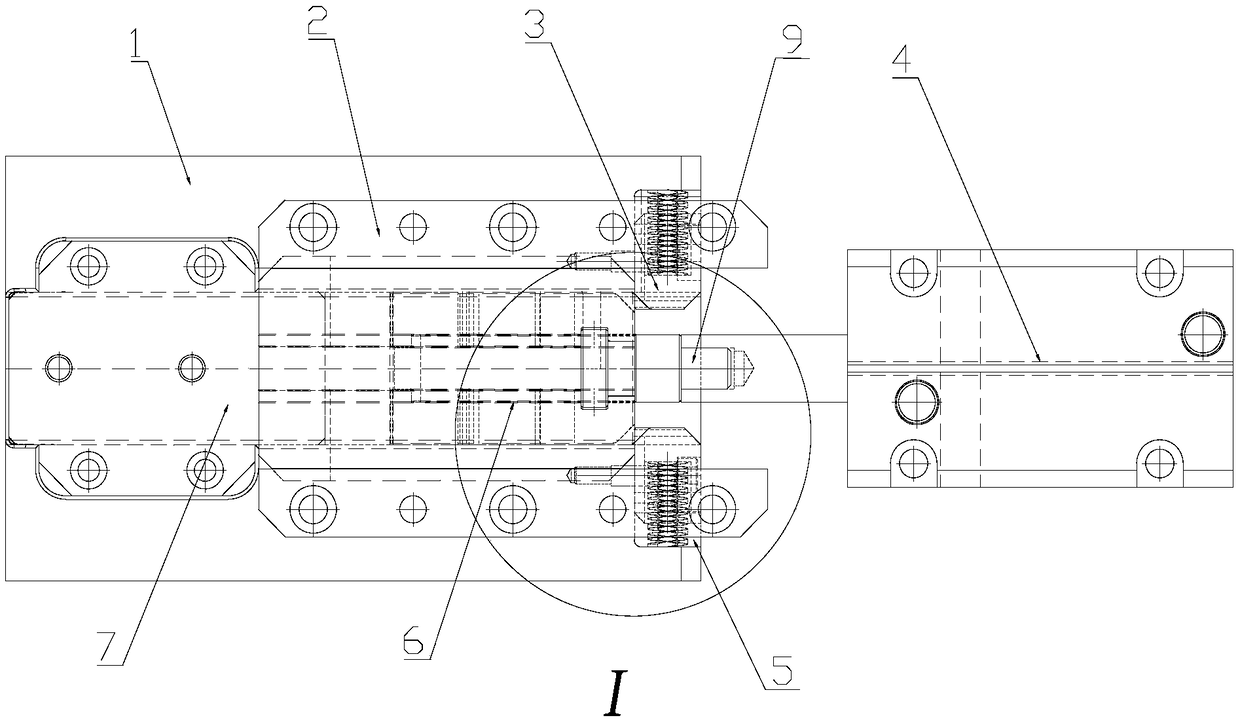
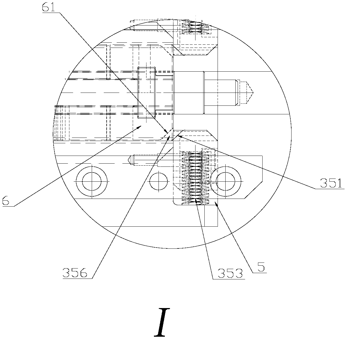
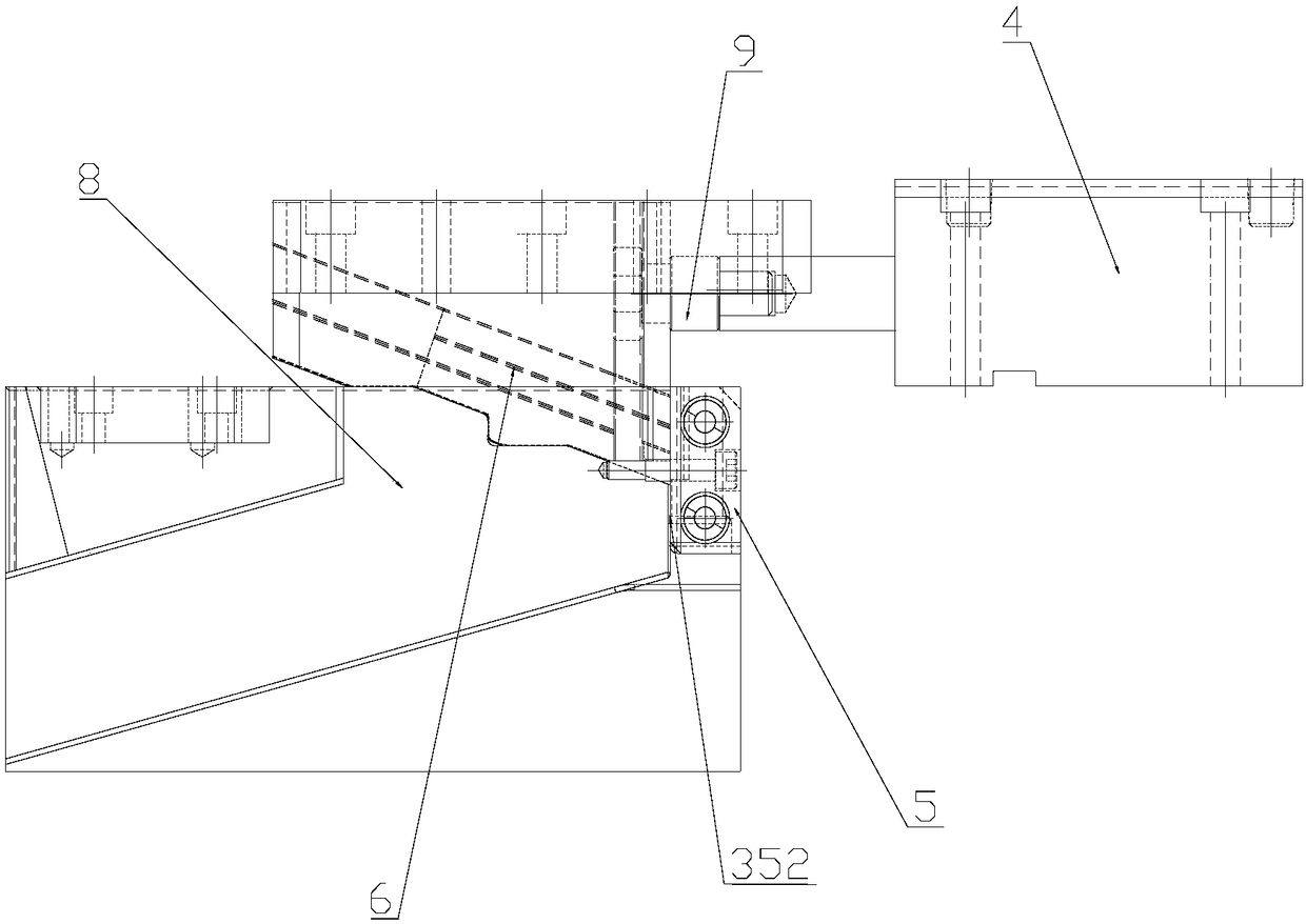
The invention provides an intra-die self-locking mechanism of a plastic die. The mechanism comprises a press strip arranged on the front die core; a switch T block; a guiding press block; and a frontdie oblique pulling member. Two sides of the guiding press block are respectively provided with a left self-locking stop block and a right self-locking stop block, which are abutted on the front die oblique pulling member. The left self-locking stop block and the right self-locking stop block are both provided with a reset spring. When die assembly is carried out, a space exists between the oblique surface of the T block and the oblique surface of the stop block. The left self-locking stop block and the right self-locking stop block are both provided with a flat vertical surface that matches with the front die oblique pulling member. A mechanical self-locking mechanism is adopted, the locking force of an oil cylinder is reduced, the size of a used oil cylinder is reduced, and the service life of the oil cylinder is prolonged. The provided intra-die self-locking mechanism has the advantages of simple operation and high efficiency, and can guarantee the stability and prevent retracting.The product processing precision and product appearance are guaranteed. The efficiency is high, and the cost is low.

Description

technical field [0001] The invention relates to the field of plastic molds, in particular to an in-mold self-locking mechanism of a plastic mold with an oblique drawing angle suitable for 0 to 45 degrees. Background technique [0002] Plastic mold is the abbreviation of a combined mold for compression molding, extrusion molding, injection, blow molding and low foam molding. A series of plastic parts of different shapes and sizes can be processed through the coordinated change of the mold convex, concave mold and auxiliary molding system. In order to overcome the expansion and opening force of the melt in the cavity to the mold during injection, the locking force applied to the mold by the injection machine will generate a force to support the mold when the raw material is injected into the cavity at high pressure, so the clamping unit of the injection molding machine must be Provide enough "clamping force" to prevent the mold from being stretched. In order to provide enough...

Claims


Application Information

Patent Timeline
Patent Type & Authority Applications(China)
IPC IPC(8): B29C45/68
CPCB29C45/68
Inventor 张祥熊军乾
Owner 伊构尔实业(苏州)有限公司
Learn More