
Micro-fluidic chip, chemiluminescent immunoassay system and analytical method

A chemiluminescence immunoassay and microfluidic chip technology, applied in the medical field, can solve the problems of high consumption of test reagents and magnetic beads, high cost, large size, etc., and achieve the effect of low chemiluminescence immunoassay and low reagent volume.

Pending Publication Date: 2019-01-15
BOE TECH GRP CO LTD +1
View PDF0 Cites 4 Cited by
  • Summary
  • Abstract
  • Description
  • Claims
  • Application Information

AI Technical Summary

Problems solved by technology

[0002] At present, immunodiagnosis is mainly carried out by chemiluminescence immunoassay analyzer. The existing instruments include immune reaction system and chemiluminescence analysis system. The immune reaction system of this instrument uses traditional reagent tubes as reaction containers, and uses micro-magnetic bead technology to analyze the reaction products. Separation from reagents requires a large amount of test reagents and magnetic beads, and because test tubes are used as reaction vessels, the amount of reagents required is large and the cost is high
[0003] In addition, the existing chemiluminescent immunoassay analyzers are large in size and inconvenient for storage

Method used


Image

  • Micro-fluidic chip, chemiluminescent immunoassay system and analytical method
  • Micro-fluidic chip, chemiluminescent immunoassay system and analytical method
  • Micro-fluidic chip, chemiluminescent immunoassay system and analytical method

Examples


Embodiment Construction

[0044] In order for those skilled in the art to better understand the technical solution of the present invention, a microfluidic chip, chemiluminescent immunoassay system and analysis method provided by the present invention will be described in detail below with reference to the accompanying drawings.

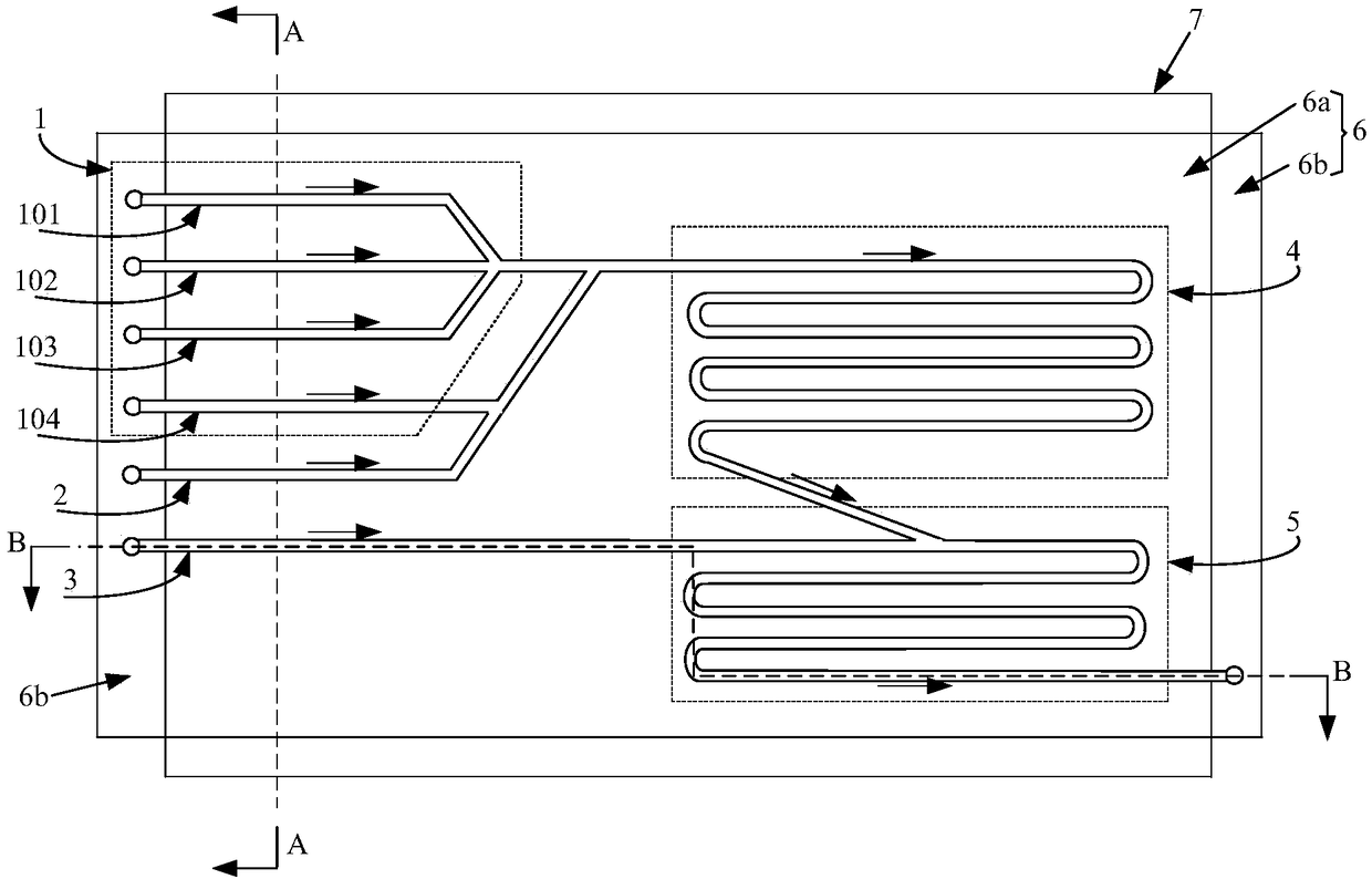
[0045] figure 1 A top view of a microfluidic chip provided in Embodiment 1 of the present invention, figure 2 for figure 1 The schematic diagram of the cross-section in the A-A direction, image 3 for figure 1 Schematic diagram of the cross-section of the B-B direction in the middle, Figure 4 It is a cross-sectional schematic diagram of the immune reaction pool, such as Figure 1 to Figure 4 As shown, the microfluidic chip is used for chemiluminescence immunoassay, which includes: a bottom plate 6, the surface of which is formed with a first liquid inlet channel 1, a second liquid inlet channel 2, a third liquid inlet channel 3, an immunoassay Reaction cell 4 and lumin...


PUM

PropertyMeasurementUnit
Diameteraaaaaaaaaa

Abstract

The invention discloses a micro-fluidic chip, a chemiluminescent immunoassay system and an analysis method. The micro-fluidic chip comprises: a base plate, on which a first liquid inlet channel, a second liquid inlet channel, a third liquid inlet channel, an immunoreaction pool and a luminescent reaction pool are formed. The discharge end of the immunoreaction pool is communicated with the liquidinlet end of the luminescent reaction pool, and the immunoreaction pool is internally equipped with a primer. The drain end of the first liquid inlet channel is communicated with the liquid inlet endof the immunoreaction pool, and the first liquid inlet channel is used for guiding a to-be-detected antigen and an antibody into the immunoreaction pool. The drain end of the second liquid inlet channel is communicated with the liquid inlet end of the immunoreaction pool, and the second liquid inlet channel is used for guiding an alkaline solution into the immunoreaction pool. The drain end of thethird liquid inlet channel is communicated with the liquid inlet end of the luminescent reaction pool, and the third liquid inlet channel is used for guiding an oxidant solution into the luminescentreaction pool. The micro-fluidic chip provided by the invention can realize chemiluminescence immunoassay with low reagent dose.

Description

technical field [0001] The invention relates to the field of medical technology, in particular to a microfluidic chip, a chemiluminescence immunoassay system and an analysis method. Background technique [0002] At present, immunodiagnosis is mainly carried out by chemiluminescence immunoassay analyzer. The existing instruments include immune reaction system and chemiluminescence analysis system. The immune reaction system of this instrument uses traditional reagent tubes as reaction containers, and uses micro-magnetic bead technology to analyze the reaction products. Separation from reagents requires a large amount of test reagents and magnetic beads, and because test tubes are used as reaction containers, the amount of reagents required is large and the cost is high. [0003] In addition, the size of the existing chemiluminescence immunoassay analyzer is relatively large, which is not convenient for storage. Contents of the invention [0004] The invention aims to solve...

Claims


Application Information

Patent Timeline
IPC IPC(8): B01L3/00G01N33/542G01N21/76
CPCG01N21/76G01N33/542B01L3/5027B01L2300/0861B01L2200/10B01L3/00B01L2300/0816B01L2300/0867B01L2300/0883B01L2300/1827B01L2400/0487G01N33/54366G01N2458/10B01L3/502715
Inventor 杨照坤邱云刘莎孙晓
Owner BOE TECH GRP CO LTD
Learn More