
A design method of bolts for engine crankshaft bushings

A design method and engine technology, applied in the field of bolt design, can solve problems such as poor accuracy and no clear design method, and achieve the effect of strong practicability and shortening the design and evaluation cycle.

Active Publication Date: 2019-01-11
CSSC POWER INST CO LTD
View PDF5 Cites 8 Cited by
  • Summary
  • Abstract
  • Description
  • Claims
  • Application Information

AI Technical Summary

Problems solved by technology

[0003] For the design of crankshaft bearing shell bolts, in the prior art, it is usually determined by experience, the accuracy is poor, and there is no clear design method

Method used


Image

  • A design method of bolts for engine crankshaft bushings
  • A design method of bolts for engine crankshaft bushings
  • A design method of bolts for engine crankshaft bushings

Examples


Embodiment Construction

[0035] In order to make the technical problems solved by the present invention, the technical solutions adopted and the technical effects achieved clearer, the technical solutions of the embodiments of the present invention will be further described in detail below in conjunction with the accompanying drawings. Obviously, the described embodiments are only the technical solutions of the present invention. Some, but not all, embodiments. Based on the embodiments of the present invention, all other embodiments obtained by those skilled in the art without making creative efforts belong to the protection scope of the present invention.

[0036] In the description of the present invention, unless otherwise clearly specified and limited, the terms "connected", "connected" and "fixed" should be understood in a broad sense, for example, it can be a fixed connection, a detachable connection, or an integrated ; It can be a mechanical connection or an electrical connection; it can be a d...


PUM


Abstract

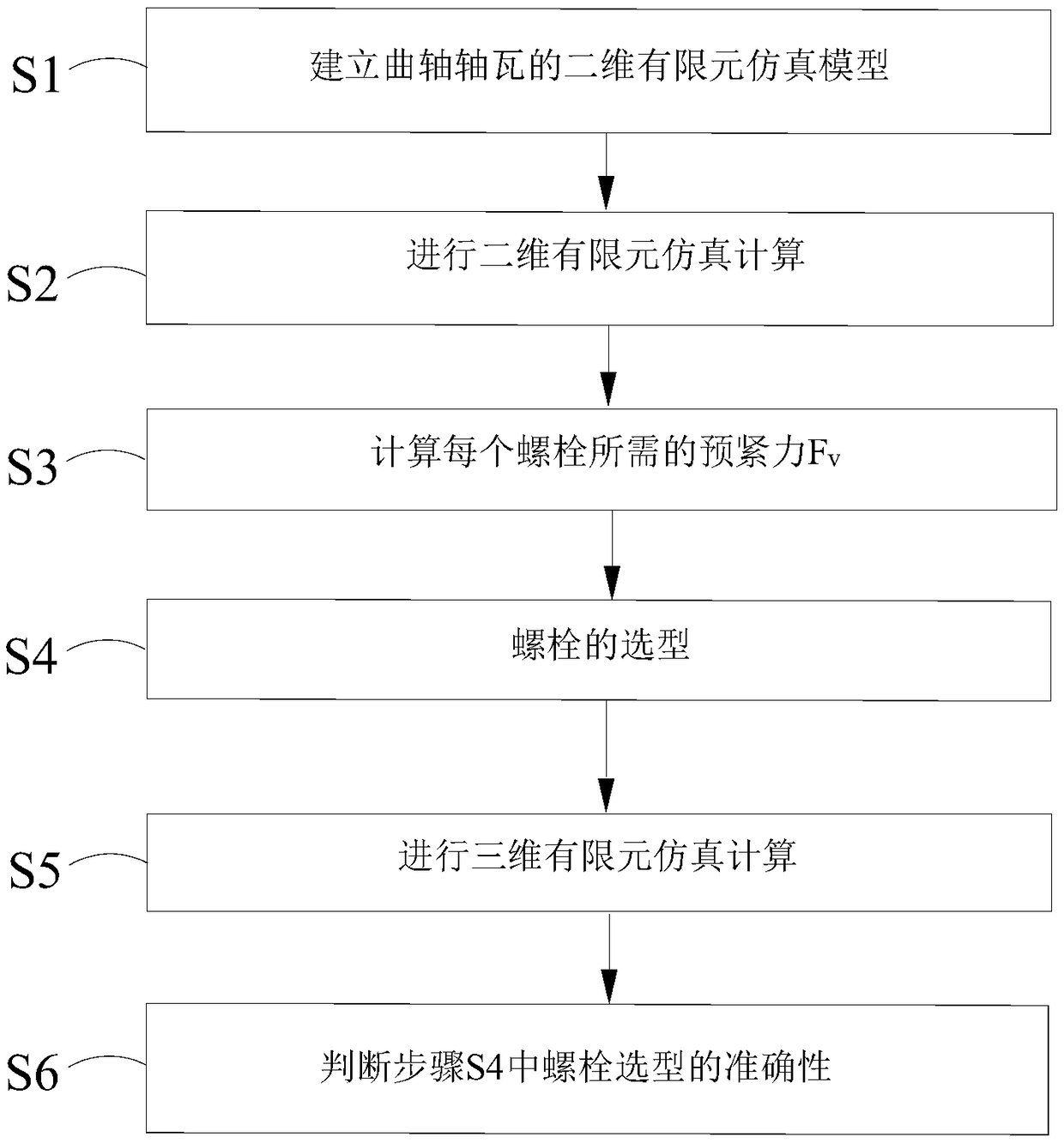
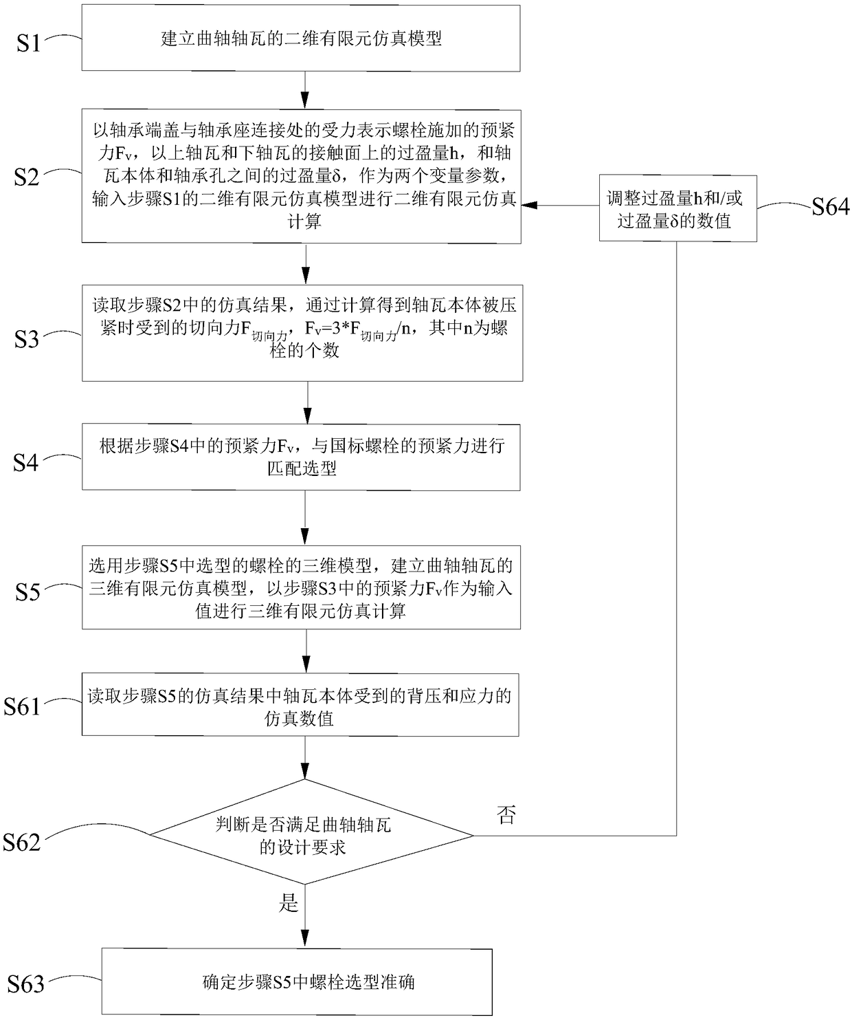
The invention discloses a design method of bolts for engine crankshaft bushings, which relates to the technical field of an engine. The crankshaft bushing comprises a bearing seat, a bearing end cap and a bushing body, wherein the bearing end cap is buckled with the bearing seat to form a bearing hole, the bushing body is arranged in the bearing hole, and the bushing body comprises an upper bushing and a lower bushing which are in snap fit. The method comprises the following steps: S1, building a two-dimensional finite element simulation model of a crankshaft bushing; S2, carrying out two-dimensional finite element simulation calculation; S3, calculating the pretightening force Fv required for each bolt; S4, selecting bolts; S5, carrying out three-dimensional finite element simulation calculation; S6, judging the accuracy of the bolt type selection in step S4. According to the parameters of different crankshaft bushings, the design method can give the size of bolts as a reference and shorten the design and evaluation cycle, and has strong practicability.

Description

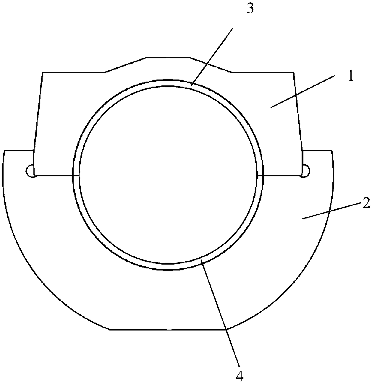
technical field [0001] The invention relates to the technical field of engines, in particular to a design method for bolts of engine crankshaft bearing bushes. Background technique [0002] During the operation of the engine, the pressure of the high-pressure gas in the cylinder is transmitted to the crankshaft through the piston and connecting rod, and then transmitted to the crankshaft bearing bush by the crankshaft through the oil film. During the process, the bearing bush and the bearing hole can be tightly combined. Such as figure 1 Shown is a schematic diagram of the structure of the crankshaft bearing pad in the prior art. The crankshaft bearing pad includes a bearing cover 1, a bearing seat 2 and a bearing shell body. The bearing end cover 1 and the bearing seat 2 are fastened to form a bearing hole, and the bearing shell body is penetrated in the bearing hole. Inside, the bearing body includes fastened upper bearing 3 and lower bearing 4, and the lower bearing 4 i...

Claims


Application Information

Patent Timeline
IPC IPC(8): G06F17/50
CPCG06F30/17G06F2119/06G06F30/23Y02T90/00
Inventor 王奎董晶瑾屠丹红
Owner CSSC POWER INST CO LTD
Learn More