
Flow-limiting non-return device with anti-siphon function

A non-return device and anti-siphon technology, used in valve devices, ventilation devices, water supply devices, etc., can solve the problems of water pollution, large volume of electromagnetic flushing valves, reducing product aesthetics and practicability, etc. The effect of saving water resources and ensuring the anti-siphon function

Pending Publication Date: 2019-01-11
COMPAS XIAMEN PLUMBING TECH
View PDF0 Cites 0 Cited by
  • Summary
  • Abstract
  • Description
  • Claims
  • Application Information

AI Technical Summary

Problems solved by technology

When the external water is cut off, the tap water pipe is in a negative pressure state. Once the electromagnetic flush valve is opened, the sewage and bacteria in the siphon pool will flow back into the tap water pipe due to the siphon effect, causing serious pollution to the water quality in the tap water piping system.
In view of the above deficiencies, a vacuum breaker is added to the upper part of the existing electromagnetic flush valve. In order to achieve anti-siphon performance, the suction port of the vacuum breaker is made larger to meet the anti-siphon requirements. In addition, because the electromagnetic flush valve is also It is necessary to install a check valve to prevent backflow, and install a flow limiter to control the flow of water under high water pressure. The above conditions lead to a large volume of the electromagnetic flush valve, which is not conducive to the smart toilet cover. The size is small and the thickness is thin, which reduces the aesthetics and practicability of the product

Method used


Image

  • Flow-limiting non-return device with anti-siphon function
  • Flow-limiting non-return device with anti-siphon function
  • Flow-limiting non-return device with anti-siphon function

Examples


Embodiment Construction

[0027] In order to make the technical problems, technical solutions and beneficial effects to be solved by the present invention clearer and clearer, the present invention will be further described in detail below in conjunction with the accompanying drawings and embodiments. It should be understood that the specific embodiments described here are only used to explain the present invention, not to limit the present invention.

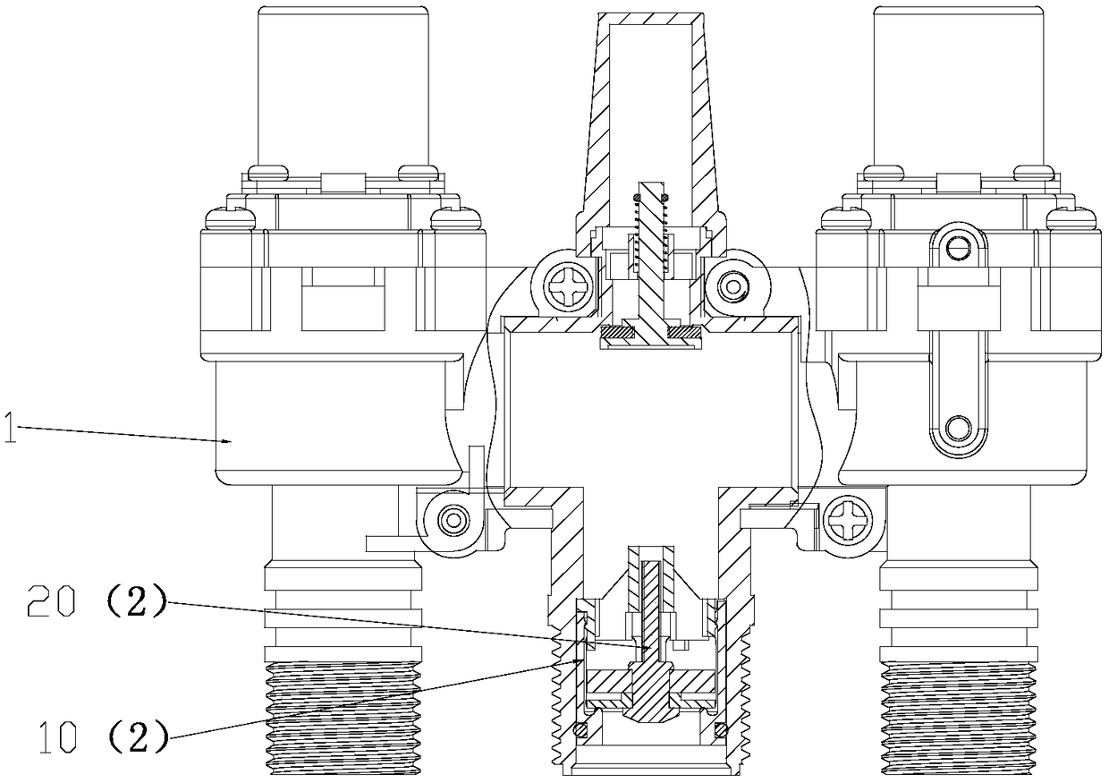
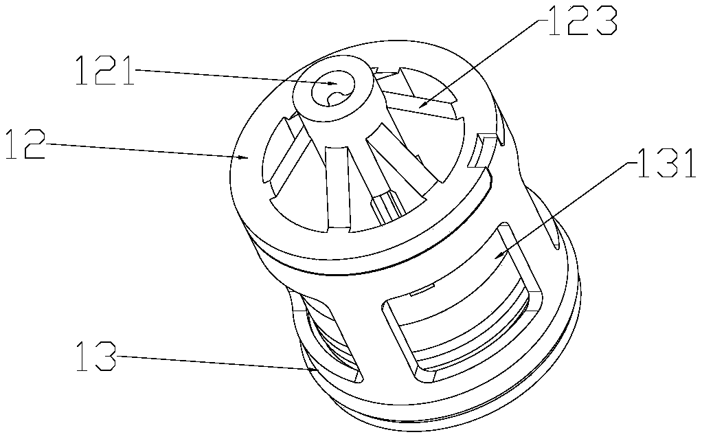
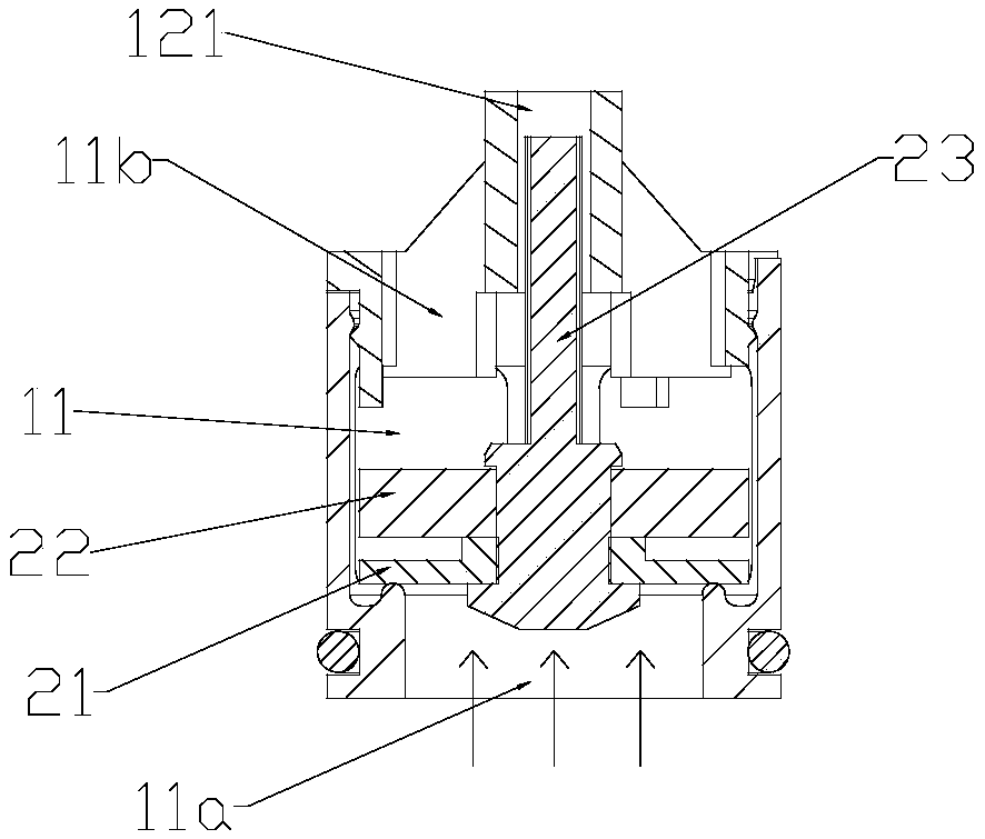
[0028] Such as Figure 1 to Figure 9 As shown, a flow limiting and non-return device with anti-siphon function includes: a valve body 1 with a water inlet channel and a water outlet channel, and a valve core assembly 2 arranged on the water inlet channel, the valve core The assembly 2 includes a body 10 with an overflow channel 11, and a valve core 20 movably arranged on the body 10, and a deformable diaphragm 21 is provided on the valve core 20 opposite to the water inlet end 11a of the overflow channel. , the valve core 20 can open or close the water...


PUM


Abstract

The invention discloses a flow-limiting non-return device with an anti-siphon function. The device comprises a valve body, and further comprises a valve element assembly; the valve element assembly comprises a body with a flow passing channel, and further comprises a valve element movably arranged on the body, a deformable membrane is arranged on one side, opposite to a water inlet end of the flowchannel, of the valve element, and the valve element can open or close the water inlet end of the flow passing channel through the membrane; and a flow limiting piece capable of adjusting a flow areaof the flow passing channel is arranged on one side, opposite to a water outlet end of the flow passing channel, of the valve element. According to the scheme, the structure is simple and compact, flow limiting and non-return functions are achieved at the same time; the deformable membrane is arranged, even if a foreign matter non-return function is destroyed between the membrane and an end faceof the water inlet end, the negative pressure enables the membrane to wrap around the foreign matter as well, so that gaps around air suction ports on the periphery of the foreign matter is enabled tobecome very small, then excurrent water can be effectively prevented from flowing back into a water supply pipeline due to the action of the negative pressure suction force, and the anti-siphon function of the valve body is guaranteed.

Description

technical field [0001] The invention relates to a current limiting and non-return device with anti-siphon function. Background technique [0002] The flushing pipe on the top of the existing non-cistern integrated intelligent toilet and the jet pipe of the bottom siphon pool are connected with the running water pipe through the electromagnetic flushing valve, and the switch of the electromagnetic flushing valve is controlled by the controller and manipulated by the control button. When the external water is cut off, the tap water pipe is in a negative pressure state. Once the electromagnetic flush valve is opened, the sewage and bacteria in the siphon pool will flow back into the tap water pipe due to the siphon effect, causing serious pollution to the water quality in the tap water piping system. In view of the above deficiencies, a vacuum breaker is added to the upper part of the existing electromagnetic flush valve. In order to achieve anti-siphon performance, the suction...

Claims


Application Information

Patent Timeline
Patent Type & Authority Applications(China)
IPC IPC(8): F16K17/20F16K15/06F16K24/02E03D9/16
CPCF16K17/20E03D9/16F16K15/06F16K24/02
Inventor 陈名琨潘胜龙
Owner COMPAS XIAMEN PLUMBING TECH
Learn More