Crushing equipment for silicon waste

A technology for crushing equipment and silicon waste, applied in grain processing and other directions, it can solve the problems of bolts and nuts not being able to be taken out normally from screw holes, bolt wear and other problems, and achieve the effect of uniform force, reliable installation and improved crushing efficiency.

Active Publication Date: 2020-10-16
CHENGDU SILICON TECH CO LTD
View PDF32 Cites 0 Cited by
  • Summary
  • Abstract
  • Description
  • Claims
  • Application Information

AI Technical Summary

Problems solved by technology

[0006] The purpose of the present invention is to provide crushing equipment for silicon waste to solve the problems in the prior art that the bolts and nuts of the single-roll crusher are worn to different degrees after being used for a period of time, and the bolts and nuts cannot be normally taken out from the screw holes. question

Method used


Image

  • Crushing equipment for silicon waste
  • Crushing equipment for silicon waste
  • Crushing equipment for silicon waste

Examples


Embodiment 1

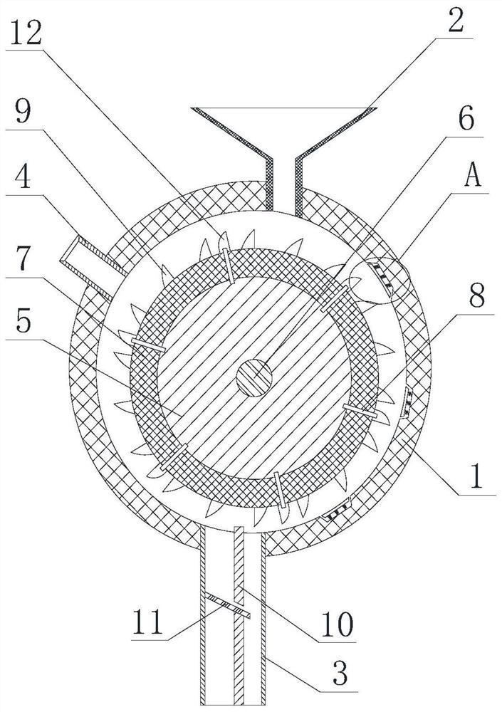
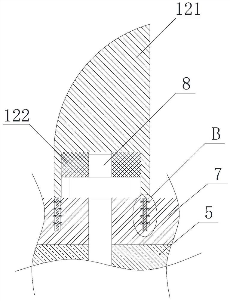
[0040] Such as figure 1 and figure 2 The shown crushing equipment for silicon waste comprises a casing 1, a feed hopper 2 is arranged on the upper part of the casing 1, a discharge pipe 3 is arranged on the bottom of the casing 1, and a roller 5 is arranged inside the casing 1, so The outer sleeve of the roller 5 is provided with a bushing 7, the bushing 7 and the roller 5 are connected by bolts 8, the bushing 7 is provided with crushing teeth 9, and the bolt 8 and the nut matched with the bolt 8 are provided with The toothed nut sleeve 12, the toothed nut sleeve 12 includes a toothed cover 121, the bottom of the toothed cover 121 is provided with an accommodation cavity, and the accommodation cavity is used to accommodate the bolts 8 and nuts located on the surface of the bushing, the accommodation cavity A snap ring 122 is arranged inside, the inner wall of the snap ring 122 presses the outer surface of the bolt 8, and the outer wall of the snap ring 122 presses the wall s...

Embodiment 2

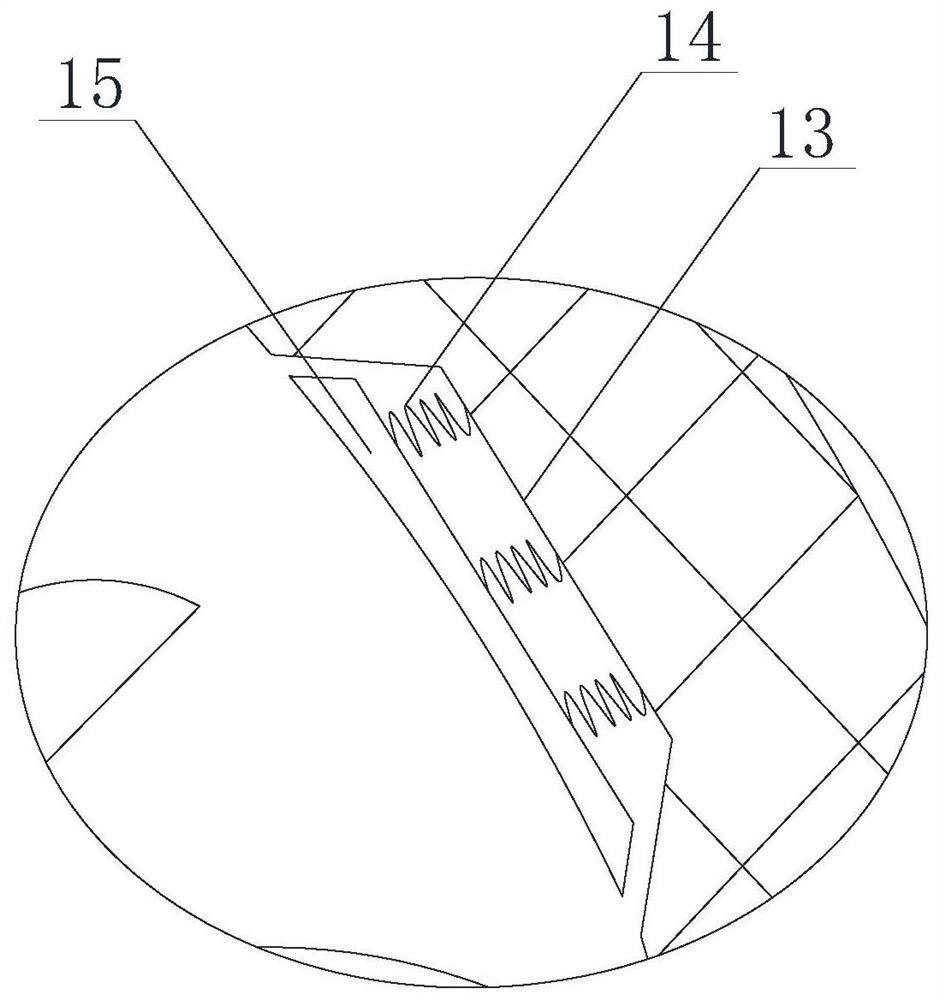
[0042] Such as image 3 and Figure 4 As shown, on the basis of Embodiment 1, the bottom end of the toothed cover 121 is provided with a clamping rod 123, and the bushing 7 is provided with a clamping groove, and the size of the clamping rod 123 matches the clamping groove The side wall of the clamping groove is provided with a rectangular groove, and the clamping rod 123 is provided with an engaging tooth 124, and the rectangular groove is used to accommodate the engaging tooth 124; the cross section of the engaging tooth 124 is a right triangle, and the right triangle sloped side down.

Embodiment 3

[0044] On the basis of Embodiment 1 and Embodiment 2, the upper part of the housing 1 is provided with a water inlet pipe 4, and the water inlet pipe 4 and the feed hopper 2 are respectively located on different sides of the vertical central axis of the housing 1; A partition 10 is provided, and the partition 10 divides the discharge pipe 3 into a drainage area and a silicon discharge area, the drainage area is close to the water inlet pipe 4, and the silicon discharge area is close to the feed hopper 2; the partition 10 A through hole is arranged on the top, and the through hole communicates with the drainage area and the silicon material area. The inner wall of the discharge pipe 3 is obliquely provided with a filter plate 11 located in the drainage area. The filter plate 11 passes through the through hole and extends to In the silicon discharge area.


PUM


Abstract

The invention discloses a crushing equipment for silicon waste. The crushing equipment for the silicon waste comprises a shell body, wherein a charge hopper is formed in the upper part of the shell body; a discharge pipe is arranged at the bottom of the shell body; a roller is arranged in the shell body; a lining sleeves outside the roller; the lining is connected with the roller through bolts; crushing teeth are arranged on the lining; tooth-shaped nut sleeves sleeve the bolts and nuts matched with the bolts; each tooth-shaped nut sleeve comprises a tooth-shaped cover; an accommodating cavityis formed in the bottom of each tooth-shaped cover; the accommodating cavities are used for accommodating the bolts and the nuts which are located on the surface of the lining; a clamping ring is arranged in each accommodating cavity; the inner wall of each clamping ring extrudes the outer surface of the corresponding bolt; the outer wall of each clamping ring extrudes the wall surface of the corresponding accommodating cavity; a groove is formed in the inner wall of the shell body; a moving plate is arranged in the groove; and a spring is arranged between the moving plate and the groove. Thecrushing equipment for the silicon waste is capable of playing a good role of double protection on the nuts and a part of the bolts which are located on the outer wall of the lining.

Description

technical field [0001] The invention relates to the field of pretreatment of silicon slag recovery, in particular to crushing equipment for silicon waste. Background technique [0002] In the industrial silicon recovery process, it is necessary to break the silicon slag into required size silicon slag for subsequent separation and smelting process. [0003] The main equipment used in the silicon slag crushing process includes cone crusher and roller crusher. Among them, the roller crusher is divided into single-roll crusher, double-roll crusher and multi-roll crusher according to the number of rollers, and divided into smooth crusher and tooth surface crusher according to the shape of the roller surface. [0004] The single-roll crusher is equipped with a roller, which is covered with a bush with crushing teeth. During operation, the roller rotates, and the silicon material between the roller and the inner wall of the shell is crushed by the extrusion of the roller and the...

Claims


Application Information

Patent Timeline
Patent Type & Authority Patents(China)
IPC IPC(8): B02C19/00B02C23/10B02C23/04B02C23/18B02C23/00
CPCB02C19/0056B02C23/00B02C23/04B02C23/10B02C23/18B02C2201/06
Inventor 羊实周旭
Owner CHENGDU SILICON TECH CO LTD
Why Eureka
Try Eureka