


Quick Research
Generate reliable direction feasibility study reports for your R&D in just a few steps.

Technical Q&A
Discover and master advanced knowledge NOW. Basics, ideas, possibilities, all at once.

Find Solutions
As an expert in R&D theories, this can generate solutions to your technical problems instantly.

Evaluate Feasibility
Analyze your overall solution with one click, know your potential R&D risks in advance.

Monitor Landscape
Get weekly tech updates, stay abreast of the latest tech innovations and key insights.
Temperature control method of electric blanket
A temperature control method and electric blanket technology, which are applied to electric heating devices, ohmic resistance heating, electrical components, etc., can solve the problems of reliability discount, difficulty in process realization, and high production cost
- Summary
- Abstract
- Description
- Claims
- Application Information
AI Technical Summary
Problems solved by technology
Method used
Image


Examples
Embodiment 1
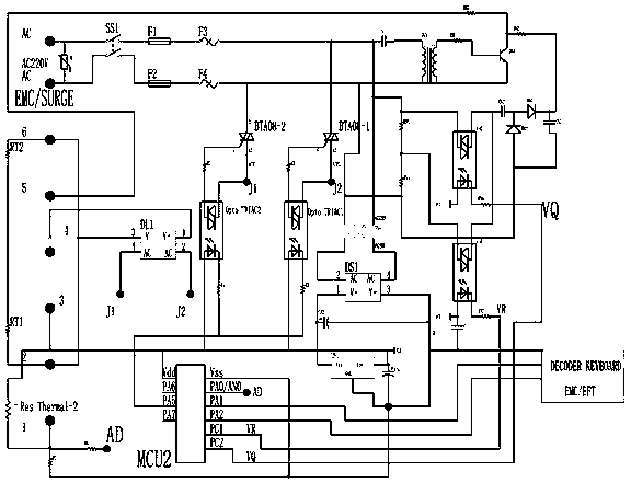
[0022] For the control device used in the temperature control method of the electric blanket in this embodiment, see figure 1 As shown, it includes the power supply for the heating wire (or wire) in the electric blanket. The power supply is connected to the control device by the mains 220V and then transformed and rectified to form a power supply output. A second temperature control processor is provided, but the first temperature sensor, the first temperature control processor and the thermal fuse which are commonly used for measuring and controlling the real-time temperature of the electric blanket are not included. A first electronic switch BTA08-1 and a second electronic switch BTA08-2 are arranged between the power supply and the heating wire, and an AND gate is formed between the first electronic switch BTA08-1 and the second electronic switch BTA08-2 (connected in series between the power supply and the heating between wires). The input ends of the first electronic swi...
Embodiment 2
[0033]The temperature control method of the electric blanket in this embodiment is an improvement on the basis of Embodiment 1, except that it is the same as Embodiment 1. The difference is:
[0034] 1) if figure 2 As shown, the second temperature sensor ResThermal-2 for measuring the real-time temperature of the environment is added, and the limit value of the ambient temperature is set in the second temperature control processor MCU2, and the real-time temperature of the environment is measured at the same time. When the real-time temperature of the environment is greater than or equal to the limit value of the ambient temperature , control the electric heating pad to stop powering on, the ambient temperature limit of this embodiment is selected to be 35°C, the ambient temperature limit is selected according to human experience, and is not limited to 35°C;
[0035] 2) if figure 2 As shown, a negative potential generating unit is added. The mains 220V is output to the neg...
PUM
 Abstract
Description
Claims
Application Information
 - R&D Engineer
- R&D Manager
- IP Professional
- Industry Leading Data Capabilities
- Powerful AI technology
- Patent DNA Extraction
Browse by: Latest US Patents, China's latest patents, Technical Efficacy Thesaurus, Application Domain, Technology Topic, Popular Technical Reports.
© 2024 PatSnap. All rights reserved.Legal|Privacy policy|Modern Slavery Act Transparency Statement|Sitemap|About US| Contact US: help@patsnap.com