Novel discharge gate structure

A technology of unloading gate and unloading door, which is applied in the direction of unloading device, etc., can solve the problems such as easy splashing of materials, and achieve the effect of solving easy splashing, simple structure and convenient use

Active Publication Date: 2019-01-08
ZHUHAI SHIGAOMA MASCH EQUIP CO LTD
View PDF12 Cites 0 Cited by
  • Summary
  • Abstract
  • Description
  • Claims
  • Application Information

AI Technical Summary

Problems solved by technology

[0003] The technical problem to be solved by the present invention is: in order to overcome the above problems, a new type of unloading gate structure is provided, which has a reasonable structure, simple structure, convenient use, good sealing performance, stability, and is not easy to jam. Effectively solve the problem that the material is easy to splash when the traditional mixer is unloading

Method used


Image

  • Novel discharge gate structure
  • Novel discharge gate structure
  • Novel discharge gate structure

Examples


Embodiment Construction

[0019] The present invention is described in further detail now in conjunction with accompanying drawing. These drawings are all simplified schematic diagrams, which only illustrate the basic structure of the present invention in a schematic manner, so they only show the configurations related to the present invention.

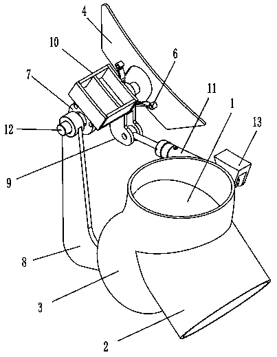
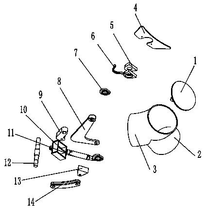
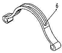
[0020] like Figure 1 to Figure 4 A novel unloading gate structure shown includes a drive part and a transmission structure, the drive part includes an oil cylinder 11, and the transmission structure includes a discharge gate 1, a discharge gate straight pipe 2, a discharge gate Door elbow 3, travel switch fixing plate 4, discharge door bearing seat 5, discharge door semicircle body 6, bearing gland 7, discharge door connecting rod 8, second discharge door connecting rod 9, discharge door bearing Seat base 10, discharge door transmission shaft 12, discharge door oil cylinder base 13 and third discharge door connecting rod 14.

[0021] The middle part of the ...


PUM


Abstract

The invention discloses a novel discharge gate structure, which comprises a driving part and a transmission structure, wherein the driving part comprises an oil cylinder; the transmission structure comprises a discharge gate, a discharge gate straight pipe, a discharge gate elbow, a travel switch fixing plate, a discharge gate bearing pedestal, a discharge gate semicircular body, a bearing gland,a discharge gate connecting rod, a second discharge gate connecting rod, a discharge gate bearing pedestal base, a discharge gate transmission shaft, a discharge gate oil cylinder base and a third discharge gate connecting rod; the middle part of the pipe wall of the discharge gate elbow and one end of the discharge gate straight pipe are opened to form T-shaped hermetical connection, and the discharge gate straight pipe is communicated with an inner cavity of the discharge gate elbow; a discharge gate is arranged on the inner cavity of the discharge gate elbow. The novel discharge gate structure disclosed by the invention is reasonable in structure, has the advantages of simple structure, convenience in use, high closure, stability, difficulty in material blocking and the like; the problem that a material is easy to sputter during discharging of a conventional stirrer is effectively solved.

Description

technical field [0001] The invention relates to the field of concrete mixing equipment, in particular to a novel discharge gate structure. Background technique [0002] It is known that when the traditional mixer is mixing materials with good fluidity, the discharge door is equipped with a large opening and poor sealing when discharging, which easily causes splashing and leakage of materials, resulting in waste of materials. Contents of the invention [0003] The technical problem to be solved by the present invention is: in order to overcome the above problems, a new type of unloading gate structure is provided, which has a reasonable structure, simple structure, convenient use, good sealing performance, stability, and is not easy to jam. It effectively solves the problem that the material is easy to splash when the traditional mixer is unloading. [0004] The technical solution adopted by the present invention to solve the technical problem is: a new type of unloading g...

Claims


Application Information

Patent Timeline
Patent Type & Authority Applications(China)
IPC IPC(8): B28C7/16
CPCB28C7/16
Inventor 郗俊峰贺咫涯周小帆
Owner ZHUHAI SHIGAOMA MASCH EQUIP CO LTD
Why Eureka
Try Eureka