
Cutting device

A cutting device and cutting piece technology, applied in metal processing and other directions, can solve problems such as easy splashing of fragments

Active Publication Date: 2021-06-25
ZHUHAI GREE INTELLIGENT EQUIP CO LTD +1
View PDF7 Cites 0 Cited by
  • Summary
  • Abstract
  • Description
  • Claims
  • Application Information

AI Technical Summary

Problems solved by technology

[0003] The main purpose of the present invention is to provide a cutting device to solve the problem that the fragments generated by the cutting operation in the prior art are easy to splash

Method used


Image

  • Cutting device
  • Cutting device
  • Cutting device

Examples


Embodiment Construction

[0031] It should be noted that, in the case of no conflict, the embodiments in the present application and the features in the embodiments can be combined with each other. The present invention will be described in detail below with reference to the accompanying drawings and examples.

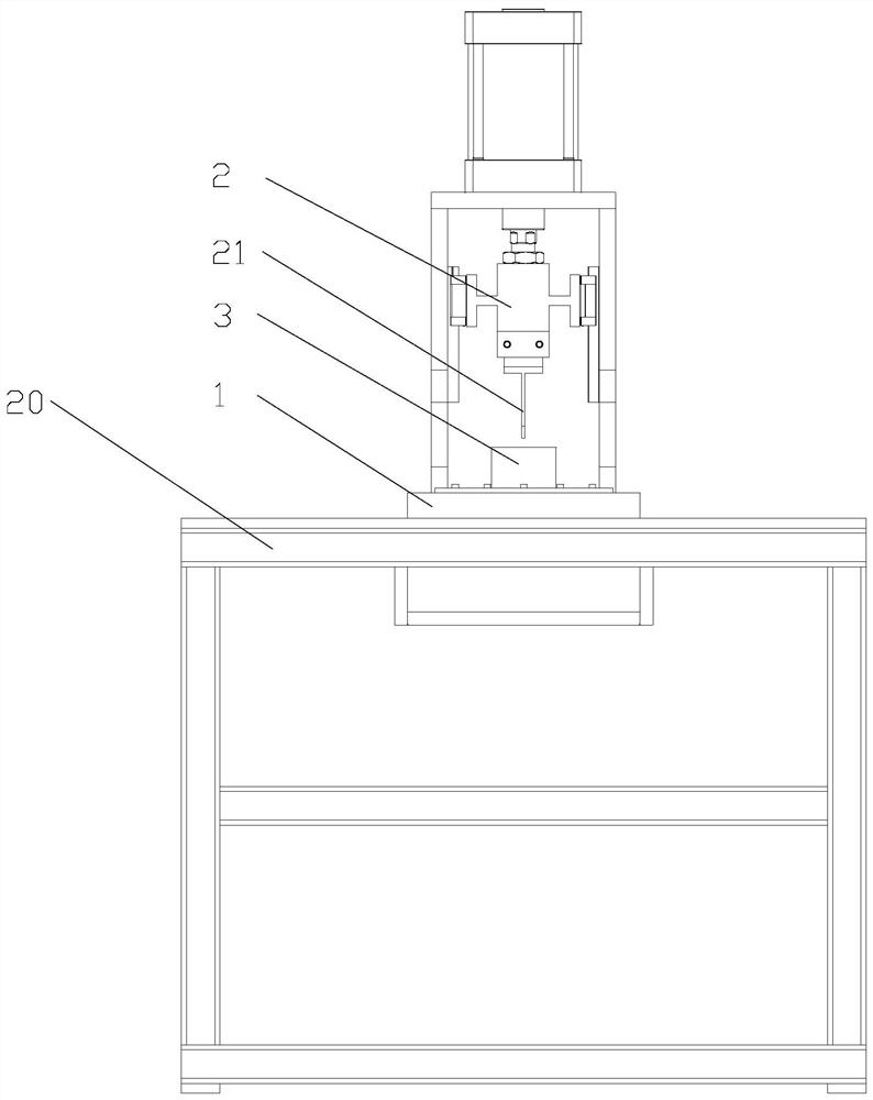
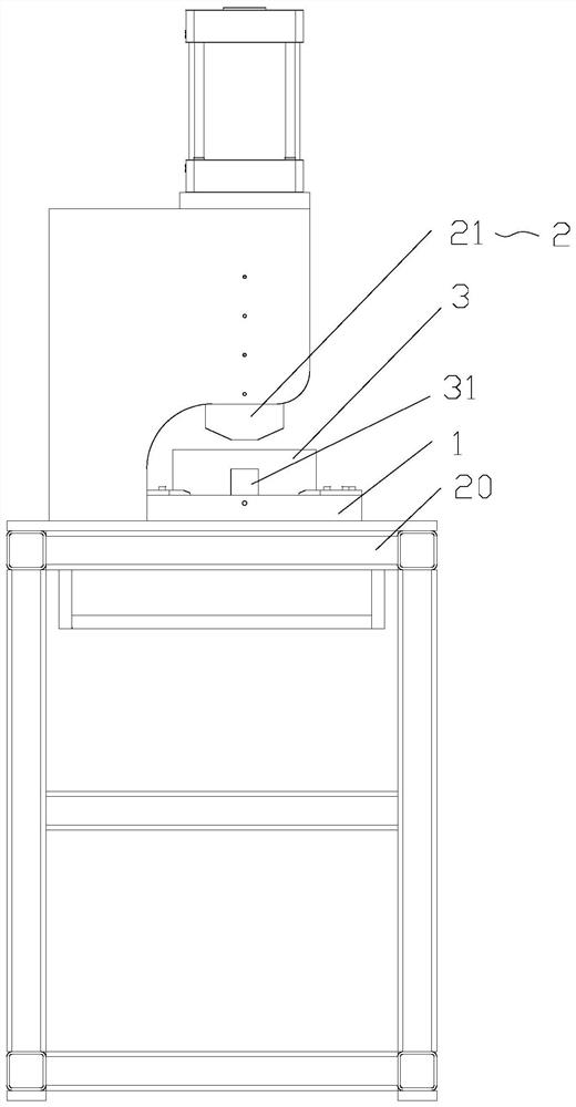
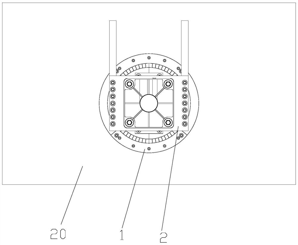
[0032] see Figure 1 to Figure 13 , the cutting device of this embodiment is used to be arranged on the workbench 20 to cut the workpiece 10 to be cut. The cutting device includes: a chassis assembly 1, the chassis assembly 1 includes a shielding part 3, and the shielding part 3 has an accommodating cavity. At least part of the cutting part 10 is arranged in the accommodating cavity; the cutting assembly 2, the cutting assembly 2 has a cutting head 21 for cutting the part 10 to be cut, and the cutting head 21 is movably arranged along a first preset direction; wherein, The cutting head 21 has an initial state away from the piece to be cut 10 and a cutting state in contact with the piece to be ...


PUM


Abstract

The invention provides a cutting device. The cutting device is used for being arranged on a workbench so as to cut a to-be-cut part. The cutting device comprises a chassis assembly and a cutting assembly. The chassis assembly comprises a shielding component; the shielding component is provided with a containing cavity; at least part of the to-be-cut part is arranged in the containing cavity; the cutting assembly is provided with a cutting tool bit used for cutting the to-be-cut part; the cutting tool bit is movably arranged in the first preset direction; the cutting tool bit has an initial state of being away from the to-be-cut part and a cutting state of making contact with the to-be-cut part; and when the cutting tool bit is in the cutting state, at least part of the cutting tool bit is arranged in the containing cavity in a penetrating manner so that the shielding component can shield the to-be-cut part. The cutting device solves the problem that fragments generated during cutting operation in the prior art are likely to splash.

Description

technical field [0001] The invention relates to the field of material cutting, in particular to a cutting device. Background technique [0002] At present, there are two main methods for cutting wire slots: wire slot cutters and manual cutting machines. When the wire groove cutter is cutting, it is easy to cause the wire groove to burst, and there is a hidden danger of fragments flying out and hurting people; the manual cutting machine works loudly, and it is easy to generate dust droplets when cutting, and there is also the hidden danger of fragments splashing, which is dangerous for personnel to operate. Greater danger. Contents of the invention [0003] The main purpose of the present invention is to provide a cutting device to solve the problem in the prior art that the debris generated by the cutting operation is easy to splash. [0004] In order to achieve the above object, the present invention provides a cutting device, which is used to be arranged on the worktab...

Claims


Application Information

Patent Timeline
IPC IPC(8): B26D7/22B26D1/06B26D7/28
CPCB26D7/22B26D1/06B26D7/28
Inventor 曲颖吴继青胡文波陆明刘帅佳
Owner ZHUHAI GREE INTELLIGENT EQUIP CO LTD
Learn More