
Transfer system of molten iron

A technology for molten iron and transfer vehicles, which is used in casting molten material containers, manufacturing tools, foundry workshops, etc., can solve the problems that need to be further improved, long waiting time, long power supply lines, etc.

Pending Publication Date: 2019-01-08
山东杰创机械有限公司
View PDF2 Cites 22 Cited by
  • Summary
  • Abstract
  • Description
  • Claims
  • Application Information

AI Technical Summary

Problems solved by technology

For example, Chinese patent CN101249560A discloses a technical scheme for utilizing molten iron transportation lines and ground molten iron tank cars to cooperate to realize the transportation of molten iron. Although this technical scheme improves the transportation efficiency of molten iron to a certain extent, the transportation efficiency needs to be further improved, especially from melting The entire transportation process from furnace to pouring needs to be further improved, and the above scheme still has the problems of long power supply lines, single function of ground molten iron tanker, and serious heat loss of molten iron during transportation
As another example, CN206286548U, a utility model patent applied by our company, discloses a molten iron transfer system. Transportation, which further improves the transportation efficiency, but this technical solution still has the problem of long waiting time during spheroidization and tilting, and the transfer system needs to be further optimized

Method used


Image

  • Transfer system of molten iron
  • Transfer system of molten iron
  • Transfer system of molten iron

Examples


Embodiment Construction

[0037] In order to explain the overall concept of the present invention more clearly, a detailed description will be given below by way of example with reference to the accompanying drawings of the specification.

[0038] In the following description, many specific details are set forth in order to fully understand the present invention. However, the present invention can also be implemented in other ways different from those described here. Therefore, the protection scope of the present invention is not limited to the specific details disclosed below. Limitations of the embodiment.

[0039] In the present invention, it should be understood that the terms "A", "B", "C", and "D" are only used for descriptive purposes, and cannot be understood as indicating or implying relative importance or implicitly indicating the indicated technology The number of features. Therefore, the features defined with "A", "B", "C", and "D" may explicitly or implicitly include one or more of the feature...


PUM


Abstract

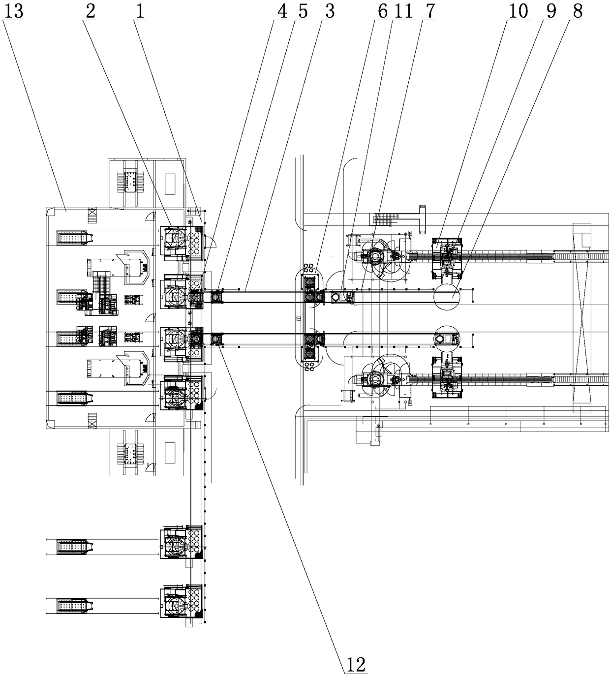
The invention relates to the technical field of molten iron transfer, in particular to a transfer system of molten iron. The system comprises a front furnace transfer rail, a plurality of melting furnaces are arranged on one side of the front furnace transfer rail along the length direction of the furnace front transfer rail, the other side is provided with a plurality of middle transfer rails which are arranged to be perpendicular to the the furnace front transfer rail, and at least one front transfer trolley used for receiving the molten iron in the melting furnaces is arranged on the frontfurnace transfer rail; middle transfer trolleys are arranged on the middle transfer rails, spheroidizing stations are arranged at the tail ends of the middle transfer rails, the spheroidizing stationsare connected with lifting tilting turning rails, and the tail ends of the lifting tilting turning rails are provided with ground rotation rails; and the ground rotating rails are connected with casting rails, casting machines are arranged at the tail ends of the casting rails, lifting tilting turning trolleys are arranged on the lifting tilting turning rails. The lifting tilting turning trolleysare used for receiving casting ladles in the spheroidizing stations, and the lifting tilting turning trolleys are used for travelling on the lifting tilting turning rails, the ground rotation rails and the casting rails to transfer the molten iron in the casting ladles into the casting machines.

Description

Technical field [0001] The invention relates to the technical field of molten iron transfer, in particular to a molten iron transfer system. Background technique [0002] The transfer of molten iron is an indispensable link in steelmaking or the production of iron products. Traditional molten iron transfer mainly relies on air transfer. The specific methods include forklift transportation and crane transportation. The existing molten iron transportation methods are relatively backward and require more In addition, due to the relatively backward transportation methods adopted, the transportation efficiency is also low. At the same time, the molten iron loses heat quickly during the transportation process, which easily causes the molten iron temperature to fail to reach the pouring temperature. standard. [0003] In order to improve the efficiency and quality of molten iron transfer, and make the design of the molten iron transfer system more reasonable and perfect, various attempts...

Claims


Application Information

Patent Timeline
IPC IPC(8): B22D47/00B22D41/12
CPCB22D41/12B22D47/00
Inventor 王德成张杰
Owner 山东杰创机械有限公司
Learn More