
Box separation frame for modeling

A shelf and unboxing technology, which is applied in the field of sand mold molding, can solve the problems of poor versatility and product scrapping, and achieve the effects of simple design, reduction of waste products, and human-made wrong boxes

Active Publication Date: 2019-01-08
济南市平阴县玛钢厂
View PDF9 Cites 2 Cited by
  • Summary
  • Abstract
  • Description
  • Claims
  • Application Information

AI Technical Summary

Problems solved by technology

[0003] The publication number is CN106694821B, which discloses a horizontal splitting injection molding machine, including a lifting and compacting mechanism, a base, a column, a first assembly, a lower sand box shuttle mechanism, a lower sand box, an upper sand box, a beam, Downward sand shooting mechanism, upper sand shooting mechanism, upper sand mold unboxing mechanism, upper limit mechanism, formwork frame and floating device, formwork frame shuttle mechanism, lower shot sand gas storage bag, upper shot sand gas storage bag, template quick change in and out and Lifting mechanism, formwork quick-change storage mechanism; the first assembly is located above the lifting and compacting mechanism; the lower sand box is located on the lower sand box shuttle mechanism, and the upper sand mold unboxing mechanism is connected to the beam, but in this device due to box off Man-made wrong boxes, resulting in scrapped products due to wrong boxes. At the same time, most of the existing unboxing devices are dedicated and have poor versatility.

Method used


Image

  • Box separation frame for modeling
  • Box separation frame for modeling
  • Box separation frame for modeling

Examples


Embodiment Construction

[0024] The following will clearly and completely describe the technical solutions in the embodiments of the present invention with reference to the accompanying drawings in the embodiments of the present invention. Obviously, the described embodiments are only some, not all, embodiments of the present invention.

[0025] Example.

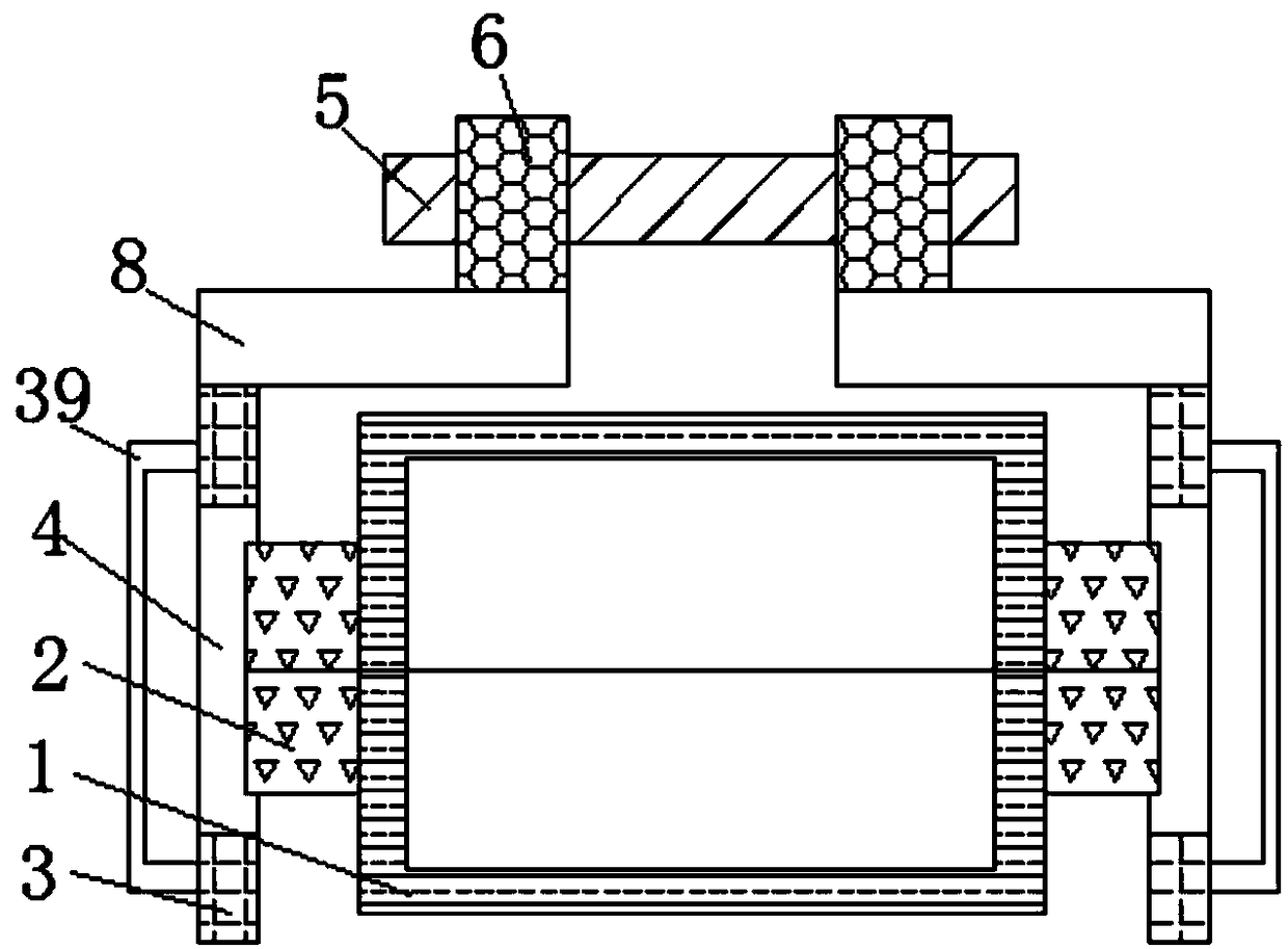
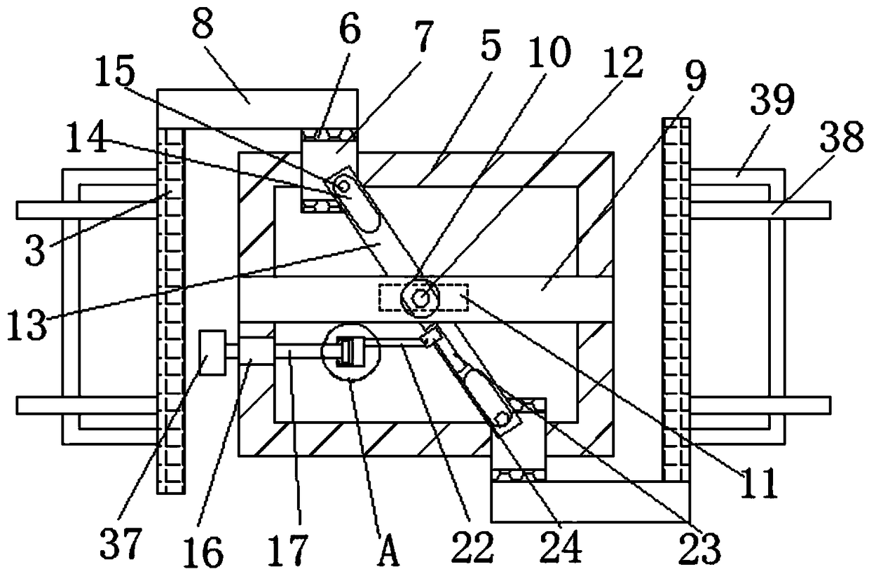
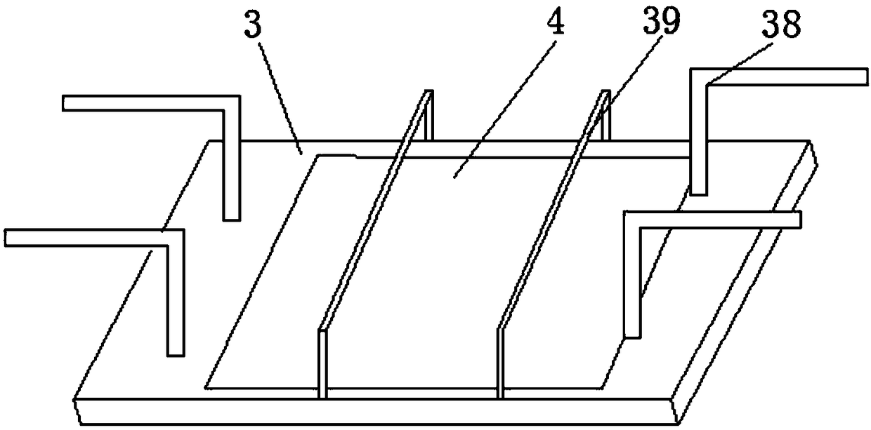
[0026] refer to Figure 1-6 , a modeling unboxing shelf, including two sandboxes 1, one sandbox 1 is placed on the top side of the other sandbox 1 correspondingly, side ears 2 are fixedly installed on both sides of the two sandboxes 1, and the sandbox 1 Both sides of the hook frame 3 are provided with a hook frame 3, and the sides where the two hook frames 3 are close to each other are provided with a hook hole 4, and the sides of the two side ears 2 that are far away from each other extend into the two hook holes 4 respectively, and the sides of the hook frame 3 There is an installation frame 5 on the top, and two sliding blocks 6 are slidably sle...


PUM


Abstract

The invention discloses a box separation frame for modeling. The box separation frame comprises two sand boxes, wherein one sand box is correspondingly placed on the top side of the other sand box; side lugs are fixedly mounted on two sides of the two sand boxes; hook racks are arranged on two sides of the sand box; hook holes are formed in mutually close sides of the two hook racks; mutually awaysides of the two side lugs respectively extend into the two hook holes; a mounting basket is arranged above the hook racks; two moving blocks are connected to the mounting basket in a sliding manner;a moving hole is formed in one side of each of the two moving blocks. The box separation frame for modeling is simple in design and convenient to operate; after the box separation frame is used, box-staggered rejected products caused by striking the sand boxes with a wooden mallet are reduced, and the casting qualification rate can be increased; manmade box staggering caused by box separation isavoided, so that rejected products caused by the manmade box staggering are reduced; meanwhile, a distance between the two hook racks can be adjusted, and a distance between two push plates can be adjusted; the box separation frame for modeling can adapt to sand boxes of different sizes and side lugs of different sizes, so that the universality of the device is improved, and demands of people aremet.

Description

technical field [0001] The invention relates to the technical field of sand mold molding, in particular to a molding unboxing shelf. Background technique [0002] Sand casting is a widely used form of casting. As the name suggests, sand is used to make molds. Sand mold casting needs to put the finished part model or wooden model (pattern) in the sand, then fill the sand around the pattern, and take out the pattern after opening the box to form the mold. [0003] The publication number is CN106694821B, which discloses a horizontal splitting injection molding machine, including a lifting and compacting mechanism, a base, a column, a first assembly, a lower sand box shuttle mechanism, a lower sand box, an upper sand box, a beam, Downward sand shooting mechanism, upper sand shooting mechanism, upper sand mold unboxing mechanism, upper limit mechanism, formwork frame and floating device, formwork frame shuttle mechanism, lower shot sand gas storage bag, upper shot sand gas stora...

Claims


Application Information

Patent Timeline
Patent Type & Authority Applications(China)
IPC IPC(8): B22C19/06B22C21/02
CPCB22C19/06B22C21/02
Inventor 张进军
Owner 济南市平阴县玛钢厂
Learn More