Silicone residue slurry treatment device

A technology of organosilicon slag slurry and treatment device, which is applied in the direction of evaporator adjustment/control, evaporator accessories, evaporation, etc., can solve the problems of low evaporation efficiency and uneven stirring of organosilicon slag slurry, and achieves increased utilization, The effect of improving the service life and improving the sealing performance

Active Publication Date: 2019-01-08
淮北亚荣科技有限公司
View PDF5 Cites 3 Cited by
  • Summary
  • Abstract
  • Description
  • Claims
  • Application Information

AI Technical Summary

Problems solved by technology

[0005] In order to make up for the deficiencies of the prior art, the present invention proposes an organosilicon slurry treatment device. The main purpose of the present invention is to solve the problem of low evaporation efficiency caused by uneven stirring of the organic silicon slurry

Method used


Image

  • Silicone residue slurry treatment device
  • Silicone residue slurry treatment device

Examples


Embodiment Construction

[0021] In order to make the technical means, creative features, goals and effects achieved by the present invention easy to understand, the present invention will be further described below in conjunction with specific embodiments.

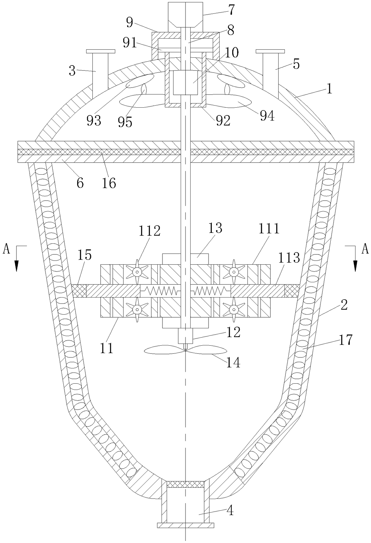
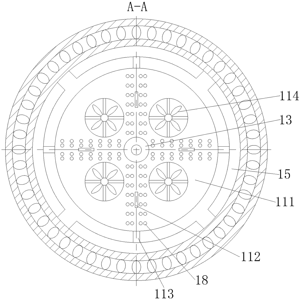
[0022] Such as Figure 1 to Figure 2 As shown, a kind of organosilicon slurry processing device according to the present invention includes a tank cover 1, a tank body 2, a feed port 3, a discharge port 4 and an air outlet 5, and the tank cover 1 is provided with a feed Port 3 and gas outlet 5, the tank cover 1 and the tank body 2 are connected by a flange 6, the tank body 2 is conical, the bottom of the tank body 2 is provided with a discharge port 4, and the tank body 2. A controller is arranged on the outside; it also includes a motor 7, a rotating shaft 8, a mounting bracket 9, a support rod 91, a support frame 92, an air bag 93, a No. 1 cylinder 10, a stirring module 11 and a support column 12. The outer layer of the tank body 2 A mud layer ...


PUM


Abstract

The invention belongs to the technical field of silicone production and in particular discloses a silicone residue slurry treatment device. The silicone residue slurry treatment device comprises a tank cover, a tank body, a feeding hole, a discharging hole and an air outlet, wherein the feeding hole and the air outlet are formed in the tank cover; the tank cover and the tank body are connected bya flange; the tank body is conical; the discharging hole is formed in the bottom of the tank body; a controller is arranged on the outer side of the tank body; the motor is arranged on a mounting bracket; the output shaft of the motor is connected with a rotating shaft; the middle of the supporting rod is fixedly connected onto the rotating shaft; the top of the support frame is fixedly connectedonto the supporting rod; the bottom of the rotating shaft is fixedly connected with a cylinder I; a telescopic rod of the cylinder I penetrates through the bottom of the support frame and is connectedwith a stirring module. According to the silicone residue slurry treatment device disclosed by the invention, the stirring module is driven to rotate by the cylinder I, and silicone residue slurry inthe tank body is stirred in a top-and-down reciprocating manner, so that the silicone residue slurry is fully stirred, and the evaporation efficiency of the device is improved.

Description

technical field [0001] The invention belongs to the technical field of organosilicon production, in particular to an organosilicon slurry treatment device. Background technique [0002] Organosilicon slurry is the waste produced during the synthesis of organosilicon monomers, especially methyl chlorosilane monomers. It is mainly composed of a large amount of high boilers and a small amount of unreacted silicon powder and copper powder brought out of the fluidized bed. , High boiler refers to the high boiling point polysilane mixture with silicon-silicon bond, silicon-carbon-silicon bond, silicon-oxygen-silicon bond, silicon-oxygen-silicon bond, silicon-silicon bond, silicon-carbon-silicon bond, silicon-oxygen-silicon bond, and a boiling range of 70.3-250 °C produced during the synthesis of methylchlorosilane monomer. . If this part of the material is exposed to the air, it will burn or form a strong acid mist or liquid. Therefore, if it is directly discharged, it will cause...

Claims


Application Information

Patent Timeline
Patent Type & Authority Applications(China)
IPC IPC(8): B01D1/00B01D1/30
CPCB01D1/0011B01D1/0082B01D1/30
Inventor 褚成亮
Owner 淮北亚荣科技有限公司
Why Eureka
Try Eureka