
Decoupling Method for Independent Inverse System of Bearingless Asynchronous Motor

An asynchronous motor, bearingless technology, used in control systems, control generators, vector control systems, etc., can solve problems such as inconvenient engineering applications, ignoring stator current dynamic equations, and complex inverse system model derivation process, to simplify the complexity. , The effect of easy engineering technology implementation and simple derivation process

Active Publication Date: 2021-07-20
HENAN UNIV OF SCI & TECH
View PDF4 Cites 0 Cited by
  • Summary
  • Abstract
  • Description
  • Claims
  • Application Information

AI Technical Summary

Problems solved by technology

Searching the existing literature and patents found that there is a complex electromagnetic coupling relationship inside the bearingless motor. For this reason, research on inverse decoupling control has been carried out at home and abroad, but the overall inverse system model and its derivation process are relatively complicated and inconvenient. Engineering application; in the inverse system modeling, most of the existing research ignores the dynamic equation of the stator current, resulting in the inverse model containing the load torque variable which is difficult to predict; in the "original system", the current component needs to be suppressed by the stator current closed loop nonlinear cross-coupling

Method used


Image

  • Decoupling Method for Independent Inverse System of Bearingless Asynchronous Motor
  • Decoupling Method for Independent Inverse System of Bearingless Asynchronous Motor
  • Decoupling Method for Independent Inverse System of Bearingless Asynchronous Motor

Examples


Embodiment Construction

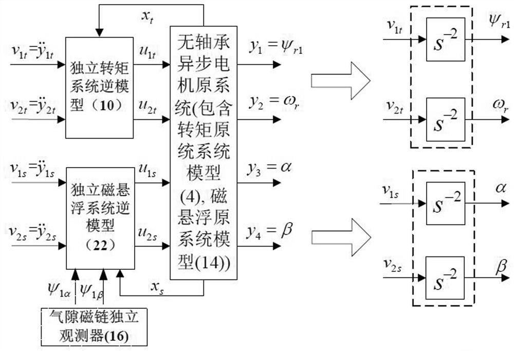
[0016] This patent takes the two-pole floating control four-pole bearingless asynchronous motor as the controlled object, and takes the rotor magnetic field orientation mode of the torque system as an example, proposes an independent inverse system decoupling method for the bearingless asynchronous motor, and simplifies the system model of the bearingless asynchronous motor The complexity of the maglev system avoids the dependence of the inverse model of the maglev system on the magnetic field orientation mode of the torque system. The specific method is, according to the original model of the independent torque system and the original model of the independent magnetic levitation system constructed according to the working principle of the bearingless asynchronous motor, respectively establish the no-load torque variable T L The inverse model of the independent torque system and the air gap flux linkage α, β axis components ψ including the independent torque system 1α and ψ 1...


PUM


Abstract

The decoupling method of the independent inverse system of the bearingless asynchronous motor, the original model of the independent torque system and the original model of the independent magnetic levitation system constructed according to the working principle of the bearingless asynchronous motor, respectively establish the no-load torque variable T L The inverse model of the independent torque system and the α and β axis components of the air gap flux linkage of the independent torque system observed by the independent observer of the air gap flux linkage ψ 1α and ψ 1β The inverse model of the independent maglev system, the cross-coupling item in the dynamic change process of the torque winding stator current has been decoupled by the inverse system method, so the current closed loop in the independent torque original system can be omitted, and the inverse system model does not contain difficult The predicted load torque variable can save the torque online identification link in the system implementation, which can effectively simplify the complexity of the overall control system structure of the bearingless asynchronous motor; using the independent inverse system decoupling method in this paper, the independent torque system inverse The model and the inverse model of the independent maglev system and their derivation process are relatively simple, which is convenient for engineering and technical realization.

Description

technical field [0001] The invention relates to the technical field of drive and control of special AC motors, in particular to a decoupling method for an independent reverse system of a bearingless asynchronous motor. Background technique [0002] Bearingless motor is a new type of motor suitable for high-speed operation based on the similarity between magnetic bearing and AC motor stator structure. It has broad application prospects in aerospace, material sealing transmission, advanced manufacturing and other fields. Searching the existing literature and patents found that there is a complex electromagnetic coupling relationship inside the bearingless motor. For this reason, research on inverse decoupling control has been carried out at home and abroad, but the overall inverse system model and its derivation process are relatively complicated and inconvenient. Engineering application; in the inverse system modeling, most of the existing research ignores the dynamic equatio...

Claims


Application Information

Patent Timeline
Patent Type & Authority Patents(China)
IPC IPC(8): H02P21/00H02P21/13
CPCH02P21/00
Inventor 卜文绍路春晓曹磊李劲伟卢盼超乔岩茹
Owner HENAN UNIV OF SCI & TECH
Learn More