Flume-type magnetic shielding structure and flat coil radio energy transmission system including the same

A magnetic shielding and shielding plate technology, applied in the direction of preventing/reducing unwanted electrical/magnetic effects, circuits, electrical components, etc., can solve problems such as environmental electromagnetic pollution, aggravating the decay rate of the coil magnetic field, and reducing the magnetic field coupling efficiency of the system , to increase the magnetic field coupling of the system, reduce the magnetic leakage of the system, and reduce the electromagnetic pollution.

Pending Publication Date: 2019-01-04
SHANGHAI UNIVERSITY OF ELECTRIC POWER
View PDF9 Cites 1 Cited by
  • Summary
  • Abstract
  • Description
  • Claims
  • Application Information

AI Technical Summary

Problems solved by technology

This structure can significantly suppress the leakage of the magnetic field in the longitudinal direction of the system, but the leakage of the stray magnetic field in the lateral direction of the system is still serious, and the addition of aluminum plates will aggravate the attenuation rate of the magnetic field between the coils, and there are still the following shortcomings:
[0004] 2. Magnetic leakage not only reduces the transmission efficiency of the system, but also generates electromagnetic radiation to the space around the system, causing environmental electromagnetic pollution;
[0005] 3. The magnetic flux leakage of the system is shielded by double-sided flat aluminum plates, which can reduce the leakage of the longitudinal magnetic field of the system, but the introduction of aluminum shielding plates will increase the attenuation rate of the internal magnetic field of the system and reduce the coupling efficiency of the system magnetic field; at the same time, the horizontal magnetic leakage level Significantly lower, but still exceeding the standard

Method used


Image

  • Flume-type magnetic shielding structure and flat coil radio energy transmission system including the same
  • Flume-type magnetic shielding structure and flat coil radio energy transmission system including the same
  • Flume-type magnetic shielding structure and flat coil radio energy transmission system including the same

Examples


Embodiment Construction

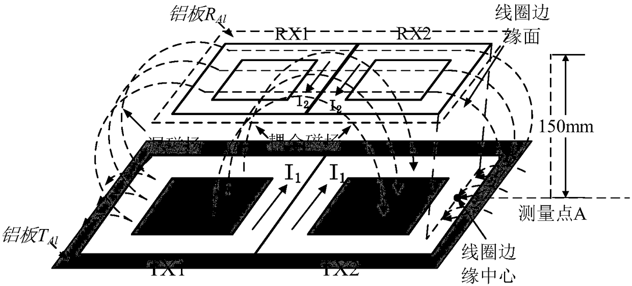
[0039] The present invention will be described in detail below in conjunction with the accompanying drawings and specific embodiments. This embodiment is carried out on the premise of the technical solution of the present invention, and detailed implementation and specific operation process are given, but the protection scope of the present invention is not limited to the following embodiments.

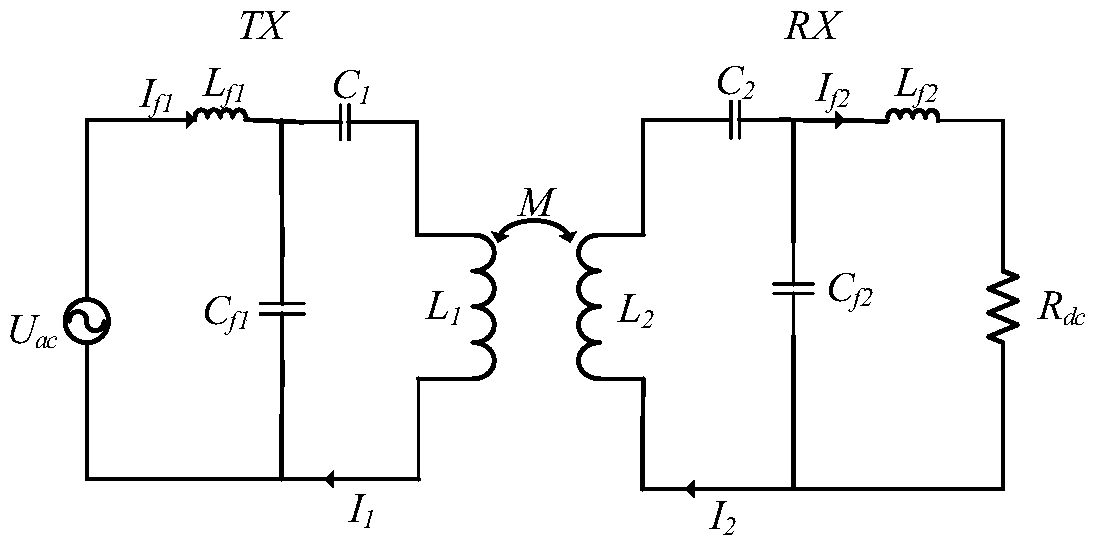
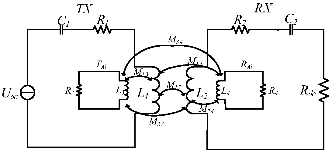
[0040] The circuit simulation model of the wireless power transfer WPT system is as follows: figure 2 shown. The co-simulation circuit of double-sided planar aluminum plate and WPT system is as follows: image 3 shown. In the figure, TX is the transmitting coil, T Al is the equivalent circuit of the primary side aluminum plate, RX is the receiving coil, R Al is the equivalent circuit of the aluminum plate on the secondary side, U ac is the high frequency power supply, R dc is the internal resistance of the power supply, L 1 , L 2 is the coil self-inductance, L f1 , L f2 is ...


PUM


Abstract

The invention relates to a flume-type magnetic shielding structure and a flat coil radio energy transmission system including the same. The water tank type magnetic shielding structure comprises a primary side shielding plate and a secondary side shielding plate. The primary side shielding plate comprises a bottom plate part and a side plate part. The bottom plate part is a flat panel with a hollow out, and the side plate part is arranged around the edge of the bottom plate part. The bottom plate and the side plate part form a water tank structure. The side plate portion comprises a side stripplate and an adjustable telescopic plate arranged in order from the bottom plate portion upward, the side strip plate is vertically connected with the bottom plate portion, and the adjustable telescopic plate and the bottom plate portion are inclined at an angle. As compare with that prior art, the invention significantly reduces the attenuation rate of the magnetic field between the primary coiland the secondary coil by hollowing out the center of the bottom plate; The lateral strip plate can restrict the transverse stray magnetic field of the system and reduce the magnetic leakage in the horizontal direction of the system. Adjustable telescopic plate can further limit the transverse stray magnetic field of the system, increase the magnetic coupling of the system, and further reduce themagnetic leakage in the horizontal direction of the system.

Description

technical field [0001] The invention relates to the technical field of wireless power transmission, in particular to a sink type magnetic shielding structure and a flat coil wireless power transmission system including the same. Background technique [0002] Wireless Power Transfer (WPT) has the characteristics of convenient and safe charging, which makes this technology develop rapidly and has been widely used in special charging fields such as electric vehicles, medical treatment, and mining. Professor Mostak Mohammad of the University of Akron uses Double-D pad (DDP) coils to wirelessly charge electric vehicles. Through the comparison and analysis of DDP coils and circular coils, it can be seen that the magnetic field of DDP coils in the system coupling space is more concentrated, and the magnetic coupling efficiency of the system is higher. higher. However, the air gap between the transmitting and receiving coils is relatively large, and the magnetic leakage of the syst...

Claims


Application Information

Patent Timeline
IPC IPC(8): H02J50/70H01F27/36H01F27/34
CPCH01F27/346H01F27/36H02J50/70
Inventor 夏能弘吴晓春
Owner SHANGHAI UNIVERSITY OF ELECTRIC POWER
Why Eureka
Try Eureka