
Multilayer packaging antenna

An antenna and lower layer technology, applied in the field of frequency tunable encapsulated antennas, can solve the problems of difficult system integration of antennas and large scale of antenna structures.

Inactive Publication Date: 2019-01-04
陈彭
View PDF4 Cites 5 Cited by
  • Summary
  • Abstract
  • Description
  • Claims
  • Application Information

AI Technical Summary

Problems solved by technology

However, as the main component of the wireless communication system, the antenna is difficult to integrate with the system
The reason is that the limitation of the communication frequency band makes the antenna structure scale relatively large

Method used


Image

  • Multilayer packaging antenna
  • Multilayer packaging antenna
  • Multilayer packaging antenna

Examples


Embodiment Construction

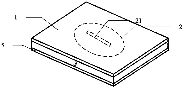
[0013] Such as figure 1 , figure 2 As shown, the present invention is a multilayer packaged antenna, which includes an upper ceramic dielectric layer 1, an upper layer copper patch 2, a low dielectric constant insulating liquid crystal layer 3, a feeding microstrip 4, and a lower ceramic dielectric layer 5.

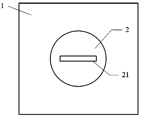
[0014] The lower surface of the upper ceramic dielectric layer 1 is attached with an upper circular copper patch 2 as a radiator, and the upper circular copper patch 2 is provided with a rectangular groove 21 (such as image 3 shown). The upper surface of the lower ceramic dielectric layer 5 is the metal feeding structure of the antenna;

[0015] The lower surface of the upper dielectric material layer 1 is attached with an upper circular copper patch 2 as a radiator. The size of the circular copper patch 2 is related to the medium wavelength of the antenna. With the increase of the antenna resonant frequency, the metal patch The size should be reduced. The patch is ...


PUM


Abstract

A multilayer packaging antenna comprises an upper dielectric layer, an upper layer metal patch, a lower dielectric constant insulating dielectric layer, a feeding microstrip, and a lower layer dielectric layer. An upper layer metal patch as a radiator is attached to the lower surface of the upper layer medium base layer, and the upper layer metal patch is provided with a groove; A low dielectric constant insulate dielectric layer is sandwiched between that upper layer dielectric layer and the lower layer dielectric layer; The upper surface of the lower layer dielectric layer is the feed structure of the antenna. The antenna can be arranged in a chip package, in particular to a frequency-adjustable packaging antenna suitable for millimeter wave communication.

Description

technical field [0001] The invention relates to an antenna which can be arranged in a chip package, in particular to a frequency adjustable package antenna suitable for millimeter wave communication. Background technique [0002] SiP technology integrates various functional modules into one package through packaging technology, which can make communication miniaturization, low cost and high stability. However, as the main component of the wireless communication system, the antenna is difficult to integrate with the system. The reason is that the limitation of the communication frequency band makes the antenna structure scale relatively large. With the rapid development of wireless communication technology, 5G communication, which aims to achieve low-latency, high-speed, and large-capacity Internet of Everything, has entered the experimental and commercial stage. 5G communication uses a large-scale multiple-input multiple-output (MIMO) antenna array to achieve beamforming. ...

Claims


Application Information

Patent Timeline
Patent Type & Authority Applications(China)
IPC IPC(8): H01Q1/38H01Q1/48H01Q1/50H01Q1/22
CPCH01Q1/2283H01Q1/38H01Q1/48H01Q1/50
Inventor 陈彭李迎松丁同禹
Owner 陈彭
Learn More