Rydberg atomic quantum coherence effect based antenna near field test probe and method

A quantum coherence and antenna technology, applied in antenna radiation patterns, measuring devices, measuring electrical variables and other directions, can solve the problems of low signal-to-noise ratio, low sensitivity, low gain, etc., and achieve high sensitivity and precision, high resolution, Sensitive effect

Inactive Publication Date: 2019-01-04
BEIJING INSTITUTE OF TECHNOLOGYGY
View PDF8 Cites 24 Cited by
  • Summary
  • Abstract
  • Description
  • Claims
  • Application Information

AI Technical Summary

Problems solved by technology

Second, the probe will disturb the field to be tested. No matter what kind of probe antenna is used, due to the existence of metal structure, it will definitely disturb the electromagnetic field formed by the antenna to be tested, and there will be multiple reflection signals between the antenna to be tested and the probe antenna
Third, the sensitivity of the probe is low
Due to the use of an electrically small-sized probe, its directivity is weak, the gain is low, and the probe needs to be separated from the antenna to be tested by three to five wavelengths during the test, resulting in weak signals received (or radiated) by the probe and low signal-to-noise ratio. It has a great impact on the accuracy of test results, especially for testing low-sidelobe and ultra-low-sidelobe antennas
Fourth, a complex and sophisticated probe scanning mechanical system is required

Method used


Image

  • Rydberg atomic quantum coherence effect based antenna near field test probe and method
  • Rydberg atomic quantum coherence effect based antenna near field test probe and method
  • Rydberg atomic quantum coherence effect based antenna near field test probe and method

Examples


Embodiment 1

[0033] In this embodiment, a probe including a probe unit is used to test the near field of the electromagnetic field of the antenna.

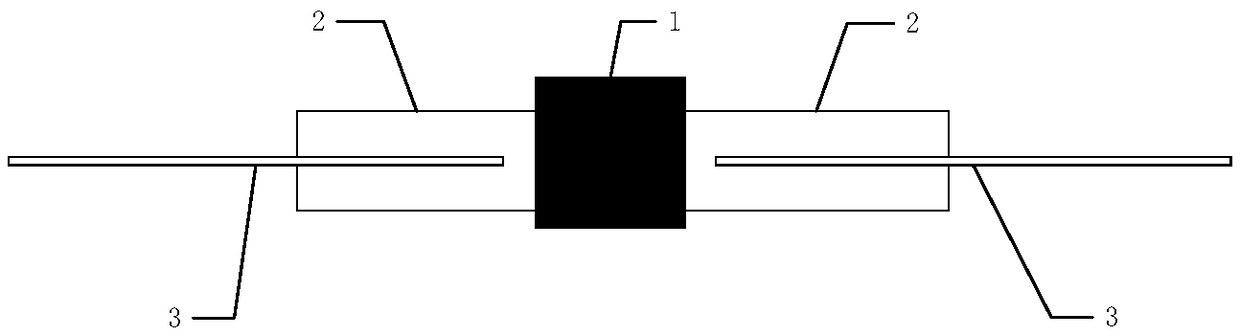
[0034] The probe used in this embodiment includes a probe unit, the probe unit, such as figure 1 As shown, it includes an alkali metal atomic gas cell, a fiber coupler and an optical fiber. The alkali metal atomic gas cell has a light-transmitting channel, and the fiber-optic coupler connects the optical fiber to the light-transmitting channel of the probe unit, injecting probe light and coupling light through the fiber The alkali metal atoms are excited to the Rydberg state, and the sensor of the probe is the atom in the Rydberg state. Among them, the alkali metal atomic gas chamber is made of ultra-high vacuum quartz atomic gas chamber technology, and the alkali metal atoms enclosed in it are mainly rubidium atoms and cesium atoms. Other types of alkali metal atoms can meet certain requirements under certain conditions. The gas cell pressur...

Embodiment 2

[0052] In this embodiment, a phase probe is added on the basis of the probe unit in Embodiment 1.

[0053] An antenna near-field test composite probe based on the Rydberg atomic quantum coherence effect, such as Figure 5 As shown, including the probe unit and the phase probe in Embodiment 1, the phase probe is composed of a semi-rigid coaxial line extending out of the inner conductor, that is, the inner conductor of the semi-rigid coaxial line extends from one end of the semi-rigid coaxial line The protruding phase probe is placed outside the atomic gas chamber, which can be attached to the epitaxy of the atomic gas chamber.

[0054] The initialization process of the composite probe and the method for measuring the electromagnetic field strength are consistent with the probe initialization and the method for measuring the electromagnetic field strength described in Embodiment 1. The difference is that when measuring the phase, the phase probe is used to accurately measure th...

Embodiment 3

[0056] In this embodiment, the probe unit is used to construct the array. The probe unit may be the probe unit in Embodiment 1, or the composite probe in Embodiment 2.

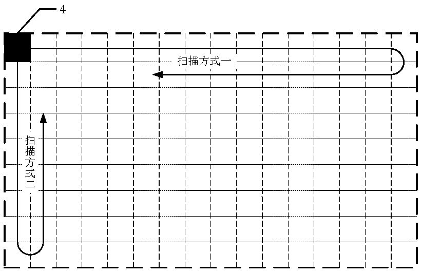
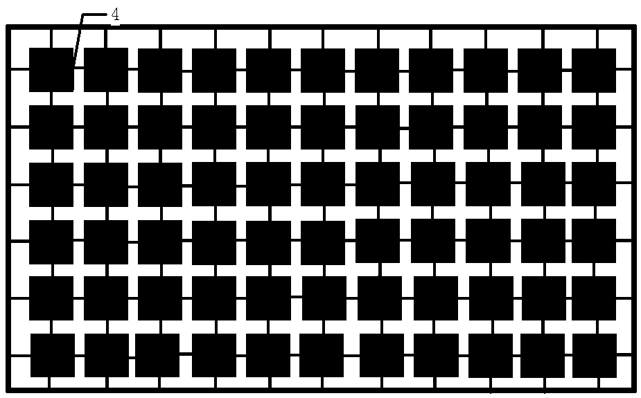
[0057] An antenna near-field test probe array based on the Rydberg atomic quantum coherence effect, such as image 3 As shown in Fig. 1, multiple probe units are used to calculate the probe layout spacing according to the Nyquist sampling law to form an antenna near-field test probe array. Since the external dimensions of the probe unit can be made very small, a probe array composed of small probe units can be constructed as a reflection of the electric field intensity in a two-dimensional space. Functionally, it is equivalent to an electromagnetic field camera, similar to a CCD array in the field of optical imaging. The smaller the single probe unit and the denser the periodic arrangement, the wider the measurable frequency range. For example, according to the Nyquist sampling law, a probe array arranged a...


PUM


Abstract

The invention discloses a Rydberg atomic quantum coherence effect based antenna near field test probe and method. A near field test of an antenna electromagnetic field can be completed by using the Rydberg atomic quantum coherence effect based antenna near field test probe and method. According to the invention, an atomic gas chamber with the Rydberg atomic quantum coherence effect is used as theantenna near field test probe. The probe has the characteristics of no error correction, high sensitivity and small disturbance to the to-be-tested antenna electromagnetic field, and can measure the electromagnetic field in the range of 1-500 GHz at one time. In addition, a precise probe space scanning mechanical system can be no longer needed by using a probe array disclosed by the invention fortesting, which can effectively reduce the test cost and improve the test efficiency. Moreover, a test process can be simplified and the test efficiency can be improved by using the composite probe added with a phase probe disclosed by the invention to test the antenna electromagnetic field.

Description

technical field [0001] The invention relates to the field of antenna near-field testing, in particular to an antenna near-field testing probe and method based on the Rydberg atomic quantum coherence effect. Background technique [0002] In the antenna near-field test, the role of the probe (Probe) is to receive (or radiate) the electromagnetic energy radiated (or received) by the antenna to be tested as a sensor at each predetermined near-field point, that is, to act as an electromagnetic near-field sensor (Sensor ). [0003] The most ideal probe is of course an ideal point source with no frequency response characteristics and no directionality, but this kind of probe is impossible to exist in practical applications, and what can be used as a probe is basically a series of small electric antennas. Since the antenna used as a probe has different capabilities of radiating or receiving electromagnetic waves at various frequency points in the frequency domain and at various ang...

Claims


Application Information

Patent Timeline
IPC IPC(8): G01R29/10
CPCG01R29/0885G01R29/10
Inventor 薛正辉任武李伟明曾庆运杨诗怡房书韬赵赫
Owner BEIJING INSTITUTE OF TECHNOLOGYGY
Why Eureka
Try Eureka