
A textile drying equipment with waste heat recovery function

A waste heat recovery and drying equipment technology, applied in lighting and heating equipment, drying, dryers, etc., can solve the problems of lowering the temperature of hot steam, affecting the effect, and large inclusions, so as to achieve sufficient contact, good effect, The drying effect is obvious

Inactive Publication Date: 2020-10-30
浙江攀越纺织品有限公司
View PDF5 Cites 0 Cited by
  • Summary
  • Abstract
  • Description
  • Claims
  • Application Information

AI Technical Summary

Problems solved by technology

[0003] When using textile drying equipment to dry textiles, the textiles are generally dried by passing hot steam into the interior of the equipment. After passing through the surface of the textiles, the hot steam will be directly discharged into the environment through the air outlet of the equipment. , due to the short contact time between hot steam and textiles, after the flow leaves, it will also contain a large amount of heat, which will be directly discharged into the environment, which will cause a large waste of energy; in addition, when the hot steam is introduced, it will pass through A fan is installed in the cavity, and the separation of the fan is used to blow, so that the fluidity of the hot steam is increased, so that the drying effect on the surface of the textile is better. However, the fan blows out cold air, which will undoubtedly reduce the temperature of the hot steam. affect the drying effect

Method used

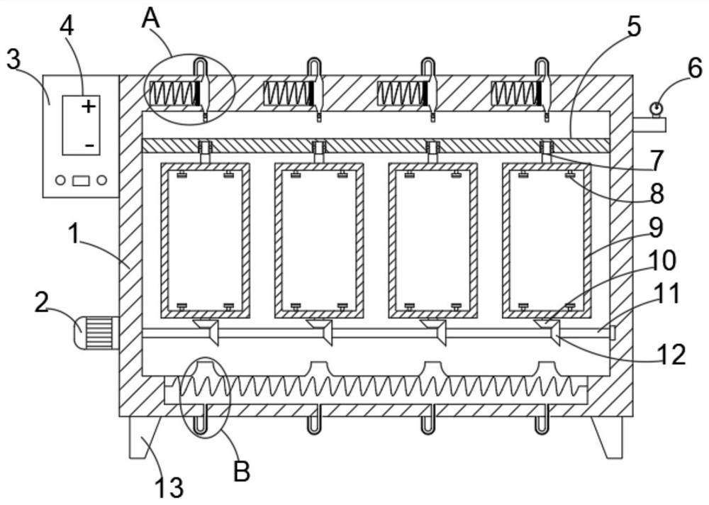
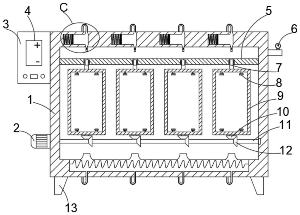
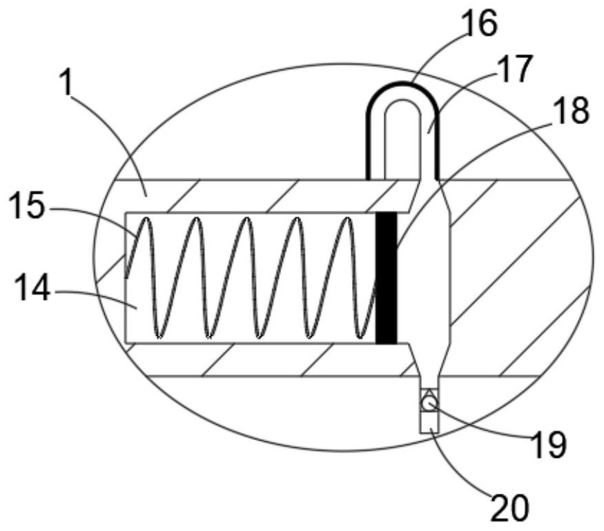

Image

  • A textile drying equipment with waste heat recovery function
  • A textile drying equipment with waste heat recovery function
  • A textile drying equipment with waste heat recovery function

Examples


Embodiment Construction

[0022] The following will clearly and completely describe the technical solutions in the embodiments of the present invention with reference to the accompanying drawings in the embodiments of the present invention. Obviously, the described embodiments are only some, not all, embodiments of the present invention.

[0023] In describing the present invention, it should be understood that the terms "upper", "lower", "front", "rear", "left", "right", "top", "bottom", "inner", " The orientation or positional relationship indicated by "outside", etc. is based on the orientation or positional relationship shown in the drawings, and is only for the convenience of describing the present invention and simplifying the description, rather than indicating or implying that the referred device or element must have a specific orientation, so as to Specific orientation configurations and operations, therefore, are not to be construed as limitations on the invention.

[0024] refer to Figure ...


PUM


Abstract

The invention discloses textile drying equipment with a waste heat recovery function. The textile drying equipment comprises a shell, the shell is of a hollow structure, and a driving motor is arranged on the side wall of one side of the shell. An output shaft of the driving motor penetrates through the side wall of the shell and is connected with a transverse rotary rod, and one side, far away from the driving motor, of the rotary rod is rotationally connected with the inner wall of the shell. A plurality of first helical gears are arranged on the side wall of the outer side of the rotary rodin a sleeved mode. A transverse fixed block is arranged in the shell, and a plurality of grooves matched with the first helical gears in quantity are formed in the side wall of the lower side of thefixed block. A bearing is arranged in each groove, and a rotary shaft matched with bearing is inserted into the bearing. A frame is arranged on the side wall of the lower side of each rotary shaft, and one side, far away from the rotary shaft, of the frame is connected with a second helical gear through a connecting rod. The textile drying equipment can recycle hot steam for drying and use the hotsteam in the drying process, and therefore energy waste is effectively prevented.

Description

technical field [0001] The invention relates to the technical field of textile drying equipment, in particular to a textile drying equipment with waste heat recovery function. Background technique [0002] As we all know, textile drying equipment is an auxiliary device for drying textiles. [0003] When using textile drying equipment to dry textiles, the textiles are generally dried by passing hot steam into the interior of the equipment. After passing through the surface of the textiles, the hot steam will be directly discharged into the environment through the air outlet of the equipment. , due to the short contact time between hot steam and textiles, after the flow leaves, it will also contain a large amount of heat, which will be directly discharged into the environment, which will cause a large waste of energy; in addition, when the hot steam is introduced, it will pass through A fan is installed in the cavity, and the separation of the fan is used to blow, so that the...

Claims


Application Information

Patent Timeline
Patent Type & Authority Patents(China)
IPC IPC(8): F26B11/18F26B21/14F26B25/02
CPCF26B11/18F26B21/14F26B25/02Y02P70/10
Inventor 汪洁
Owner 浙江攀越纺织品有限公司
Learn More