Hand-held spinning type steel bar binding device

A steel bar binding and spin-type technology, which is applied in construction, building structure, and construction material processing, can solve the problems of workers' physical discomfort, etc., and achieve the effect of labor-saving installation, eliminating the need for rotating operation steps, and easy operation

Pending Publication Date: 2019-01-04
唐山曹妃甸二十二冶工程技术有限公司
View PDF7 Cites 0 Cited by
  • Summary
  • Abstract
  • Description
  • Claims
  • Application Information

AI Technical Summary

Problems solved by technology

Wrists and arms are sore after working every day, causing workers to feel unwell

Method used


Image

  • Hand-held spinning type steel bar binding device
  • Hand-held spinning type steel bar binding device
  • Hand-held spinning type steel bar binding device

Examples


Embodiment Construction

[0026] Below in conjunction with embodiment, further illustrate the present invention.

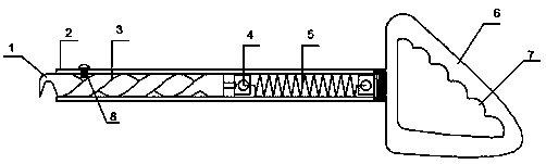
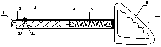
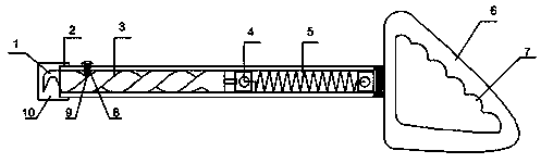
[0027] see figure 1 , a hand-held spin-type steel bar binding device is composed of a binding hook 1, an outer rod 2, an inner screw rod 3, a rod end spring fixing piece 4, a tension spring 5 and a guide bolt 8; the rod body is provided with an outer rod 2, an inner The screw rod 3, the outer rod 2 is a cavity structure, the cavity of the outer rod 2 is provided with an inner screw rod 3, a tension spring 5, one end of the inner screw rod 3 is connected and fixed with the binding hook 1; the other end of the inner screw rod 3 Through the rod end spring fixed piece 4 and one end of the tension spring 5 hinged, the other end of the tension spring 5 is connected and fixed with the outer rod 2; the side wall of the outer rod 2 is provided with a guide hole, and the guide bolt 8 is fixed in the guide hole, The bottom end of the guide bolt 8 is inserted into the groove of the inner screw, and w...


PUM


Abstract

The invention discloses a hand-held spinning type steel bar binding device comprising a binding hook and a rod body. The rod body is provided with an outer rod having a cavity structure; an inner spiral rod is arranged in the cavity of the outer rod; one end of the inner spiral rod is fixedly connected with the binding hook and the other end of the inner spiral rod is hinged to one end of an extension spring by a rod end spring fixing piece; and the other end of the extension spring is fixed and connected with the outer rod. A guiding hole is formed in the side wall of the outer rod; a guidingbolt is fixed in the guiding hole; and the bottom of the guiding bolt is inserted and sleeved in an inner spiral groove. The inner spiral rod rotates under limiting by the guiding bolt; and thus thebinding hook is driven by the rotation of the inner spiral rod to rotate by using the axis of the inner spiral rod as the center. The hand-held spinning type steel bar binding device has advantages oflabor saving, simple operation, and high portability; automatic rotating binding is realized; the manual rotation operation step is saved; the steel bar binding efficiency is improved under the circumstance of intensive binding buckles; the steel bar binding quality is ensured on the premise that the construction period is accelerated; and a phenomenon that the wrist and arm ache because of long-time handle rotation in the prior art is avoided.

Description

technical field [0001] The invention relates to a building construction auxiliary device, in particular to a hand-held self-rotating steel bar binding device. Background technique [0002] The handle of the existing steel bar tying hook is in the shape of a cylinder, and the end of the rod is bent at an angle of 30°. The bearing structure in the handle is convenient for the rod end to rotate. During operation, insert the hook at the end of the rod into the tying thread buckle, and rotate the handle to achieve the purpose of tying. . In the actual binding operation process, because there are relatively many buckles, the worker will rotate the handle 3-5 times every time a buckle is tied during the steel bar binding process. After working every day, the wrists and arms are sore, causing the workers to feel unwell. Contents of the invention [0003] The technical problem to be solved by the present invention is to provide a hand-held spin-type steel bar tying device, which ...

Claims


Application Information

Patent Timeline
Patent Type & Authority Applications(China)
IPC IPC(8): E04G21/12
CPCE04G21/123
Inventor 杨海亮苑博峰时志宇孟晶晶
Owner 唐山曹妃甸二十二冶工程技术有限公司
Why Eureka
Try Eureka