A non-cooperative target satellite-rocket docking ring capturing mechanism and a capture method thereof
A non-cooperative target and docking ring technology, which is applied to the non-cooperative target star-arrow docking ring capture mechanism and its capture field, can solve the problems of narrow application range, low integration, and large volume, and achieve short capture time and high integration , small size effect
- Summary
- Abstract
- Description
- Claims
- Application Information
AI Technical Summary
Problems solved by technology
Method used
Image
Examples
specific Embodiment approach 1
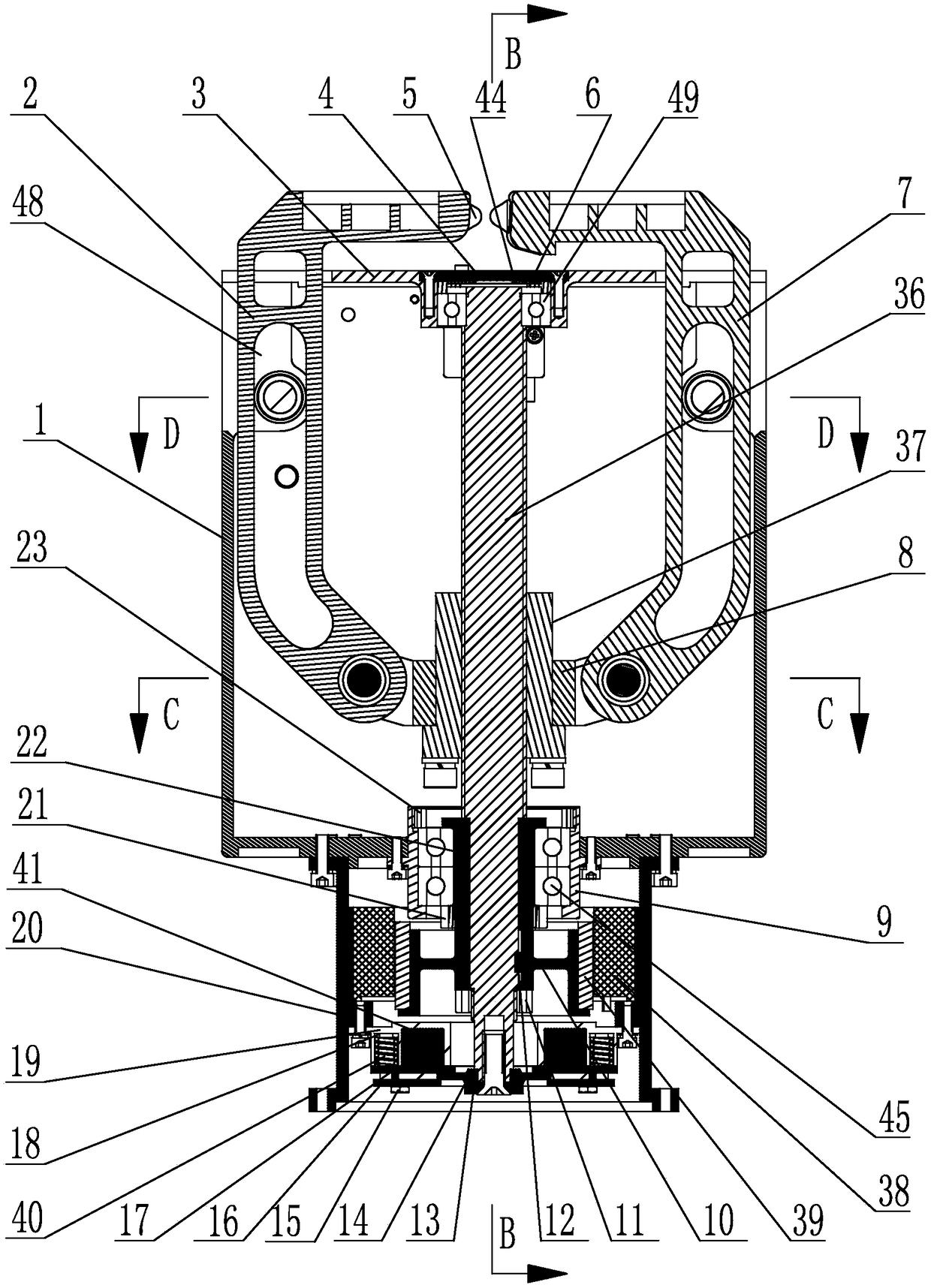
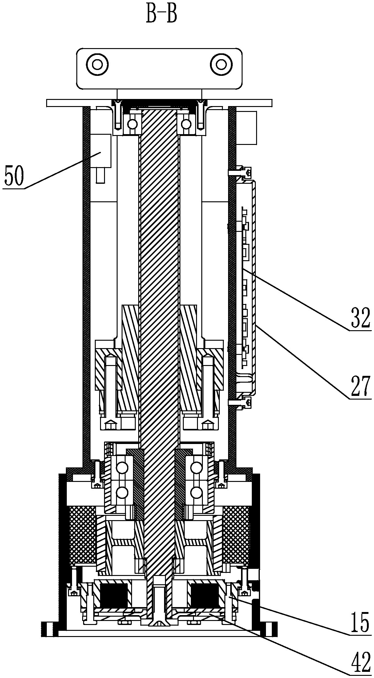
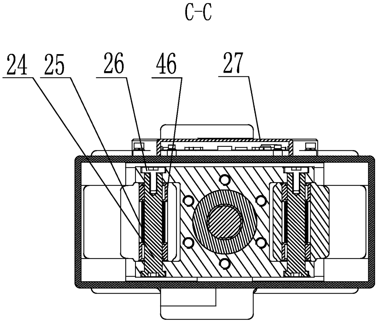
[0034] Specific implementation mode one: as figure 1 with figure 2 As shown, the non-cooperative target satellite docking ring capture mechanism of this embodiment includes an upper support shell 1, an inner capture finger 2, an upper cover plate 3, an outer capture finger 7, an adapter 8, a motor rotor shaft 10, and a brake assembly , the lower supporting shell 20, the ball screw shaft 36, the screw nut 37, the motor stator 38 and the motor rotor 39; the upper supporting shell 1 is a rectangular parallelepiped shell, and the lower supporting shell 20 is fixed on the On the lower end face, the upper cover plate 3 is fixed on the upper end face of the upper support case 1, the ball screw shaft 36 is vertically installed on the upper support case 1 and the lower part of the ball screw shaft 36 is located on the lower support case 20 Inside, the lead screw nut 37 is mounted on the ball screw shaft 36 and is located in the upper support housing 1, the adapter 8 is fixedly sleeve...
specific Embodiment approach 2
[0038] Specific implementation mode two: as figure 1 As shown, the non-cooperative target star-rocket docking ring capture mechanism in this embodiment also includes a deep groove ball bearing cover 4, a disc spring support pad 6, a deep groove ball bearing 49 and a disc spring 44, and the center of the upper cover plate 3 is processed with Bearing support hole, the deep groove ball bearing 49 is installed in the bearing support hole of the upper cover plate 3, the disc spring 44 is arranged on the upper end surface of the deep groove ball bearing 49 through the disc spring support pad 6, and the deep groove ball bearing cover 4 is passed through the screw Connected to the top cover. Such a design can effectively compensate the influence of the deformation of the ball screw shaft 36 caused by the temperature change. Other components and connections are the same as those in the first embodiment.
[0039] The deep groove ball bearing 49 is installed in the bearing support hole...
specific Embodiment approach 3
[0040] Specific implementation mode three: as figure 1 As shown, the non-cooperative target star-arrow docking ring capture mechanism in this embodiment also includes a bearing seat 9, an angular contact ball bearing inner ring lock nut 21, an angular contact ball bearing inner support sleeve 22, an angular contact ball bearing outer ring lock Tight nut 23 and two angular contact ball bearings 45, the bearing housing 9 is fixedly installed in the central through hole at the bottom of the upper supporting shell 1, the inner support sleeve 22 of the angular contact ball bearing is fixedly sleeved on the bottom of the ball screw shaft 36, and the two Two angular contact ball bearings 45 are set back-to-back on the inner support sleeve 22 of the angular contact ball bearings, two angular contact ball bearings 45 are located in the bearing housing 9, and the lower end of the bearing housing 9 is locked by the locking nut 21 of the inner ring of the angular contact ball bearing The ...
PUM
 Abstract
Description
Claims
Application Information
 - R&D
- Intellectual Property
- Life Sciences
- Materials
- Tech Scout
- Unparalleled Data Quality
- Higher Quality Content
- 60% Fewer Hallucinations
Browse by: Latest US Patents, China's latest patents, Technical Efficacy Thesaurus, Application Domain, Technology Topic, Popular Technical Reports.
© 2025 PatSnap. All rights reserved.Legal|Privacy policy|Modern Slavery Act Transparency Statement|Sitemap|About US| Contact US: help@patsnap.com


