Compression device and installation structure of small arm casting and reducer synchronous wheel assembly

A technology of pressing device and installation part, which is applied in metal processing, manipulators, metal processing equipment, etc. It can solve the problems that the pressing device cannot work synchronously with the manipulator, and the installation of the synchronous wheel assembly of the reducer and the forearm casting is not in place, etc.

Pending Publication Date: 2019-01-04
SUZHOU RS TECH
View PDF8 Cites 0 Cited by
  • Summary
  • Abstract
  • Description
  • Claims
  • Application Information

AI Technical Summary

Problems solved by technology

[0004] Therefore, the technical problem to be solved by the present invention is that the existing pressing device cannot work synchronously with the manipulator in ...

Method used


Image

  • Compression device and installation structure of small arm casting and reducer synchronous wheel assembly
  • Compression device and installation structure of small arm casting and reducer synchronous wheel assembly
  • Compression device and installation structure of small arm casting and reducer synchronous wheel assembly

Examples


Embodiment 1

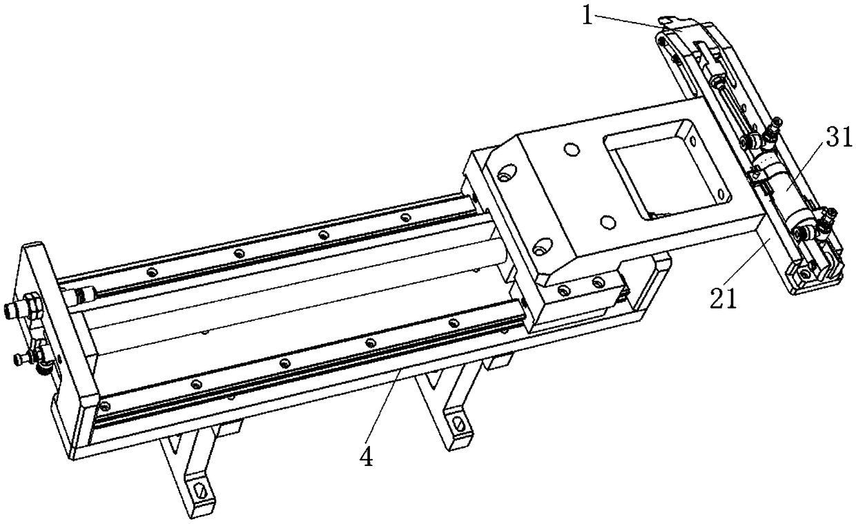
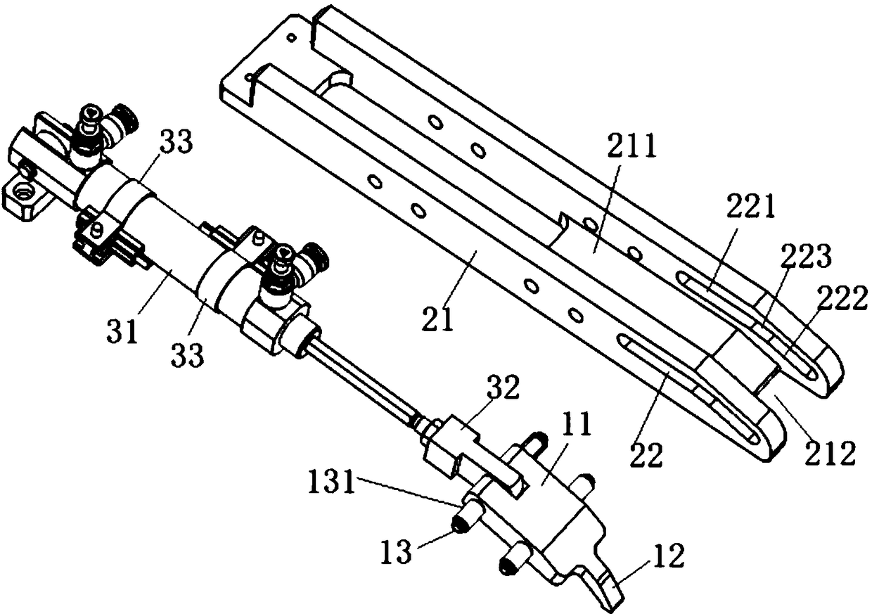
[0046] This embodiment provides a pressing device, such as Figure 1 to Figure 5As shown, it includes a motion conversion component, a pressure head 1 , a first driver 31 and a base 21 .

[0047] Such as figure 1 As shown, the motion conversion component includes a sliding slot 211 disposed on the base 21 with the notch facing upwards, and one and opposite guide holes 22 are respectively provided on the two side walls of the sliding slot 211 . Wherein, the indenter 1 is driven by the first driver 31 to be slidably arranged in the chute 211, and the two ends of the indenter 1 are respectively slidably arranged in a guide hole 22, but the bottom of the indenter 1 is in contact with the guide hole 22. The bottom of the chute separates.

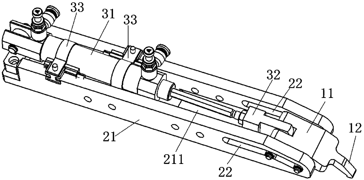
[0048] Such as figure 2 As shown, the first driver 31 is installed in the chute and its telescopic shaft performs telescopic movement along the chute 211. For example, the first driver 31 is an air cylinder, and the ram 1 is connected to the ...

Embodiment 2

[0068] This embodiment provides an installation structure of the forearm casting and the synchronous wheel assembly of the reducer, including a workbench, two pressing devices in Embodiment 1, and a manipulator. Among them, the workbench is set horizontally, and the two pressing devices are relatively arranged above the workbench; the manipulator is used to pick and place the forearm casting and the synchronous wheel assembly of the reducer on the workbench.

[0069] With the installation structure of this embodiment, when it is necessary to install the reducer synchronous wheel assembly on the forearm casting, first place the forearm casting on the workbench, and use the manipulator to vertically embed the reducer synchronous wheel assembly into the forearm casting In the inner hole; at the same time, the pressure head 1 of the two pressing devices in Embodiment 1 extends into the inner hole of the forearm casting along the horizontal direction, and applies a downward pressing...


PUM


Abstract

The invention discloses a compression device and an installation structure of a small arm casting and a reducer synchronous wheel assembly. The compression device comprises moving transforming parts and a pressure head, the moving transforming parts are provided with guiding faces extending horizontally, the pressure head is driven by a first driver and can be slidably arranged on the guiding faces, and the pressure head is guided by the guiding faces and transforms from initial horizontal motion into motion with at least motion components in the vertical direction. The installation structureincludes the compression device and a manipulator. Under the action of the vertical motion components, the pressure head moves downward and exerts downward compressive force on to-be-compressed parts,the space occupied by the compression device in the vertical direction is reduced, thus the compression device and the vertical operating manipulator can operate synchronously above the to-be-compressed parts, and the accuracy of assembling of the to-be-compressed parts and other parts is ensured.

Description

technical field [0001] The invention relates to the technical field of robot assembly, in particular to a pressing device and an installation structure of a forearm casting and a reducer synchronous wheel assembly. Background technique [0002] In the prior art, when installing the forearm casting of the robot and the reducer synchronous wheel assembly, the reducer synchronous wheel assembly needs to be embedded in the inner hole at one end of the forearm casting, in order to make the reducer synchronous wheel assembly and the forearm casting When it is installed in place, it is necessary to apply a downward pressing force to the synchronous wheel assembly of the reducer through the pressing device, so as to embed the synchronous wheel assembly of the reducer into the inner hole of the small arm casting. [0003] The pressing device in the prior art adopts a vertically arranged cylinder and a pressing plate fixed on the bottom of the vertical telescopic shaft of the cylinder...

Claims


Application Information

Patent Timeline
IPC IPC(8): B23P19/02B25J9/00
CPCB23P19/02B25J9/00
Inventor 吴加富缪磊许新星冯小平
Owner SUZHOU RS TECH
Why Eureka
Try Eureka