
Low-cost miniature narrow pulse generating method

A narrow pulse, low-cost technology, applied in the electronic field, can solve the problems of high frequency of crystal oscillator, high price of FPGA, poor pulse time stability, repeatability and interchangeability, etc., and achieve the effect of flexible configuration and stable pulse width of the system

Pending Publication Date: 2019-01-01
TIANJIN UNIV
View PDF0 Cites 2 Cited by
  • Summary
  • Abstract
  • Description
  • Claims
  • Application Information

AI Technical Summary

Problems solved by technology

However, FPGA is expensive and has a large package, so it has no advantages in applications with fewer channels and high volume requirements; CPLD requires a higher frequency of crystal oscillator because it does not have a built-in phase-locked loop, and it has fewer channels than FPGA. There is no advantage in applications with high volume requirements; the scheme of gate circuit competition and risk has the disadvantages of poor pulse time stability, repeatability and interchangeability because the pulse width depends on the delay time of the gate circuit

Method used


Image

  • Low-cost miniature narrow pulse generating method
  • Low-cost miniature narrow pulse generating method
  • Low-cost miniature narrow pulse generating method

Examples


Embodiment Construction

[0015] The present invention will be described in detail below in conjunction with the accompanying drawings and embodiments.

[0016] The narrow pulse signal generation method of the present invention uses the delay line and the narrow pulse generation method of the exclusive OR gate, and obtains the narrow pulse signal by comparing the undelayed signal and the delayed signal.

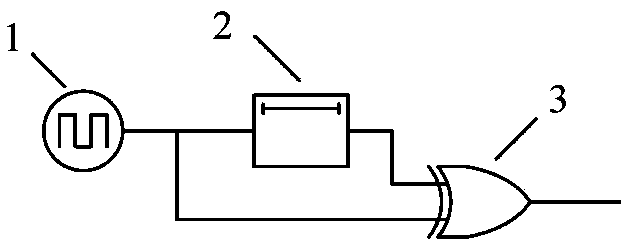
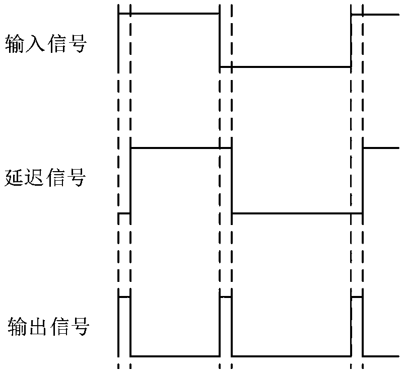
[0017] A narrow pulse generating system such as figure 1 As shown, the external PWM excitation source 1 is connected to the delay line module 2, and the delayed signal and the original signal pass through the exclusive OR gate 3 to obtain the final output narrow pulse signal. Wherein, the delay line module 2 uses a delay line chip, and its delay parameters are determined according to the required pulse width. Such as figure 2 As shown, when the input source is reversed, due to the existence of the delay line, the other input signal of the logic gate has not been reversed. Under the XOR logic, 3 out...


PUM


Abstract

The present invention relates to a low-cost miniature narrow pulse generating method, and an employed circuit comprises an excitation source for generating a PWM excitation signal, a delay line moduleand an exclusive OR gate comparator. The method is characterized in that according to the required pulse width of the narrow pulse, the delay parameter of the delay line module is determined, and thePWM excitation signal is used as the original signal; the delay signal of the delay line module and the original signal pass through the exclusive XOR gate comparator to obtain a narrow pulse signalwhich is finally outputted. The method has the advantages of low cost and good stability.

Description

technical field [0001] The invention belongs to the field of electronic technology and relates to a low-cost and miniaturized narrow pulse generation method. Background technique [0002] Narrow pulse signals are widely used in many fields, such as pulsed laser drive, step test, etc., and the pulse width is mostly at ns level or below. The traditional narrow pulse methods include thyratrons, avalanche tube arrays and high-speed switches, etc., but the pulse waveforms obtained by these methods are not good, the harmonics are large, and some voltage amplitudes are extremely high, which are only suitable for driving laser devices. The suitability is not high. At the same time, there are also digital methods, such as using FPGA and CPLD to generate pulse waveforms, or using gate circuits to compete and take risks. However, FPGA is expensive and has a large package, so it has no advantages in applications with fewer channels and high volume requirements; CPLD requires a higher ...

Claims


Application Information

Patent Timeline
Patent Type & Authority Applications(China)
IPC IPC(8): H03K5/156H03K5/06
CPCH03K5/06H03K5/156H03K2005/00058
Inventor 段发阶林昊然蒋佳佳傅骁李旭叶德超
Owner TIANJIN UNIV
Learn More