
Medical trash incineration device

A technology of waste incineration and incineration device, applied in incinerators, combustion methods, combustion types, etc., can solve the problems of virus and bacteria breeding, inability to completely eliminate virus and other pollution, labor-consuming and other problems, to prevent the spread of viruses and bacteria, The effect of reducing the spread of viruses and bacteria and reducing the volume

Inactive Publication Date: 2019-01-01
六安市智奇工业设计有限公司
View PDF5 Cites 2 Cited by
  • Summary
  • Abstract
  • Description
  • Claims
  • Application Information

AI Technical Summary

Problems solved by technology

[0002] Medical waste includes infectious waste, infectious waste, medical equipment waste, expired pharmaceutical and chemical waste, etc. Therefore, it needs to go through a series of treatment processes such as high-temperature incineration. The environment has caused serious pollution. Among the methods of treating medical waste, incineration is the most common method. However, most of the traditional medical waste incineration equipment is put into the incinerator for incineration at one time, resulting in incomplete incineration and unable to completely eliminate the virus. pollution, and the volume of the input garbage is too large, it must be put in multiple times, which is labor-intensive, or most incinerators cannot guarantee that it will be carried out in a closed space during the process of garbage treatment and incineration, which will cause a lot of waste. Growth of virus bacteria

Method used

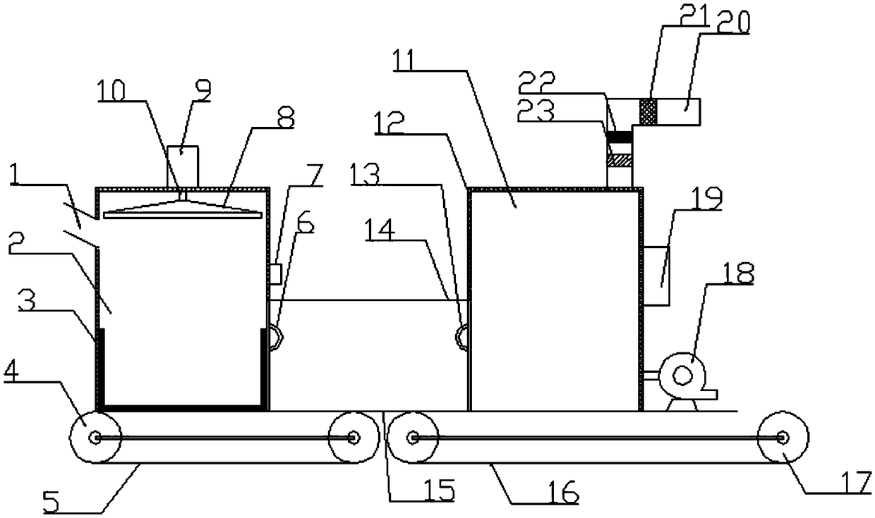
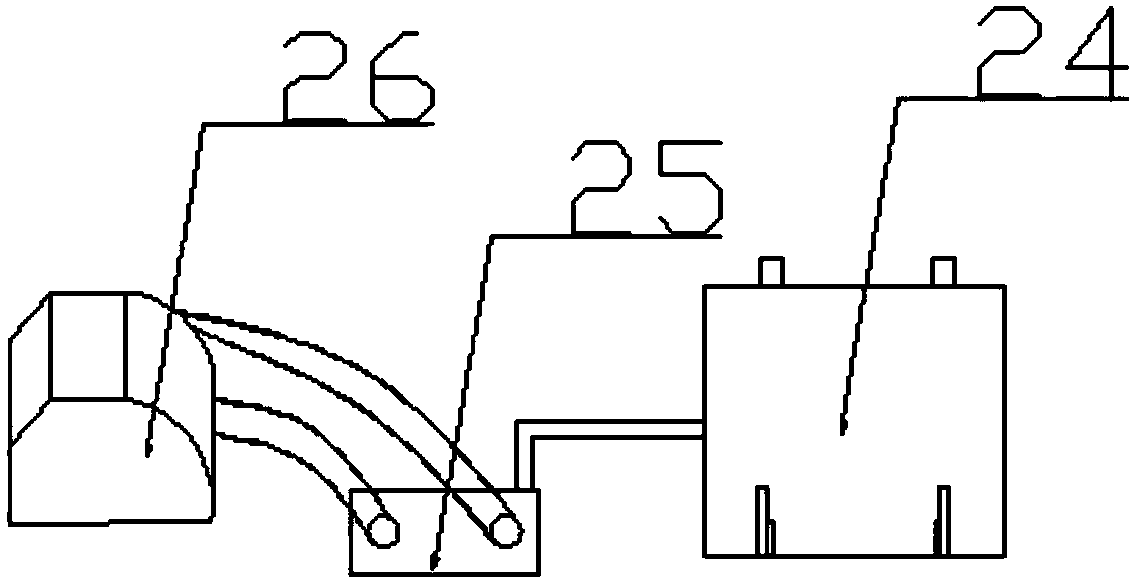
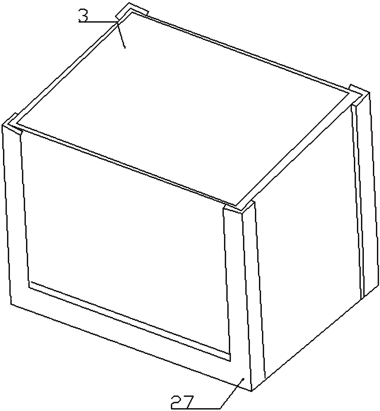

Image

  • Medical trash incineration device
  • Medical trash incineration device
  • Medical trash incineration device

Examples


Embodiment Construction

[0018] The technical solution of this patent will be further described in detail below in conjunction with specific embodiments.

[0019] Embodiments of the present patent are described in detail below, examples of which are shown in the drawings, wherein the same or similar reference numerals designate the same or similar elements or elements having the same or similar functions throughout. The embodiments described below by referring to the figures are exemplary and are only used for explaining the patent, and should not be construed as limiting the patent.

[0020] In the description of this patent, it is to be understood that the terms "center", "upper", "lower", "front", "rear", "left", "right", "vertical", "horizontal", The orientation or positional relationship indicated by "top", "bottom", "inner", "outer", etc. is based on the orientation or positional relationship shown in the drawings, and is only for the convenience of describing this patent and simplifying the des...


PUM


Abstract

The invention provides a medical trash incineration device, and belongs to the field of environment-friendly devices. The medical trash incineration device comprises a feeding furnace and an incineration furnace. A feeding port is formed in the upper portion of the left side of the feeding furnace. A material storage box is arranged at the bottom end of the inner portion of the feeding furnace. Afirst conveyor belt is arranged at the bottom of the feeding furnace. First electric rolling wheels are arranged at the two ends of the first conveyor belt. An extrusion device is arranged at the topend of the inner portion of the feeding furnace. A feeding furnace automatic lifting door is arranged on the lower right portion of the feeding furnace. An incineration furnace automatic lifting dooris arranged on the lower left portion of the incineration furnace. A second conveyor belt is arranged at the bottom of the incineration furnace. Second electric rolling wheels are arranged at the twoends of the second conveyor belt. An air blower is arranged on the lower right portion of the incineration furnace. The medical trash incineration device is simple in structure and flexible and convenient to use, trash which is put in can be extruded and smashed, the size is reduced, subsequent incineration can also be more thorough, the trash can automatically enter the incineration furnace afterbeing put in, manual contact is not needed, spreading of viruses and bacteria is reduced, and the whole trash conveying process is in a closed space all the time so that spreading of the viruses andthe bacteria can be prevented.

Description

technical field [0001] The invention relates to the technical field of environmental protection, in particular to a medical waste incineration device. Background technique [0002] Medical waste includes infectious waste, infectious waste, medical equipment waste, expired pharmaceutical and chemical waste, etc. Therefore, it needs to go through a series of treatment processes such as high-temperature incineration. The environment has caused serious pollution. Among the methods of treating medical waste, incineration is the most common method. However, most of the traditional medical waste incineration equipment is put into the incinerator for incineration at one time, resulting in incomplete incineration and unable to completely eliminate the virus. pollution, and the volume of the input garbage is too large, it must be put in multiple times, which is labor-intensive, or most incinerators cannot guarantee that it will be carried out in a closed space during the process of ga...

Claims


Application Information

Patent Timeline
Patent Type & Authority Applications(China)
IPC IPC(8): F23G7/00F23G5/033F23G5/12F23G5/44
CPCF23G7/00F23G5/033F23G5/12F23G5/444F23G2201/80F23G2204/103F23G2209/20
Inventor 孙益博
Owner 六安市智奇工业设计有限公司
Learn More