
An induction heating device for gear surface quenching and a gear surface quenching method

An induction heating device and induction heating technology, applied in the field of heat treatment, can solve the problems of low heating efficiency and large energy consumption demand, and achieve the effects of improving production efficiency, safety, and heating depth

Active Publication Date: 2019-12-27
河北瑞丰科技有限公司
View PDF10 Cites 0 Cited by
  • Summary
  • Abstract
  • Description
  • Claims
  • Application Information

AI Technical Summary

Problems solved by technology

In order to improve the uniformity of the temperature distribution on the surface of the gear and thus improve the uniformity of the effective hardened layer distribution, the imitation tooth coil is often used to heat the workpiece as a whole or to scan and move the heating by tooth by tooth. The energy consumption of the overall heating method is huge. For large The production cost is too high for heavy-duty gears, and the heating efficiency of scanning and moving heating by profiling coils is low. In addition, during the gear meshing process, according to the distribution of meshing lines, the wear degree of the gear surface is different, and the gear tooth surface The wear at the meshing position is more serious, and the induction hardening layer not only needs to meet the requirements for tooth surface wear, but also needs to meet the gear strength design. For the top, a thicker effective hardened layer distribution is required to improve the wear resistance of the gear and prolong the service life of the gear

Method used


Image

  • An induction heating device for gear surface quenching and a gear surface quenching method
  • An induction heating device for gear surface quenching and a gear surface quenching method
  • An induction heating device for gear surface quenching and a gear surface quenching method

Examples


Embodiment Construction

[0029] The present invention will be further described below in conjunction with accompanying drawing:

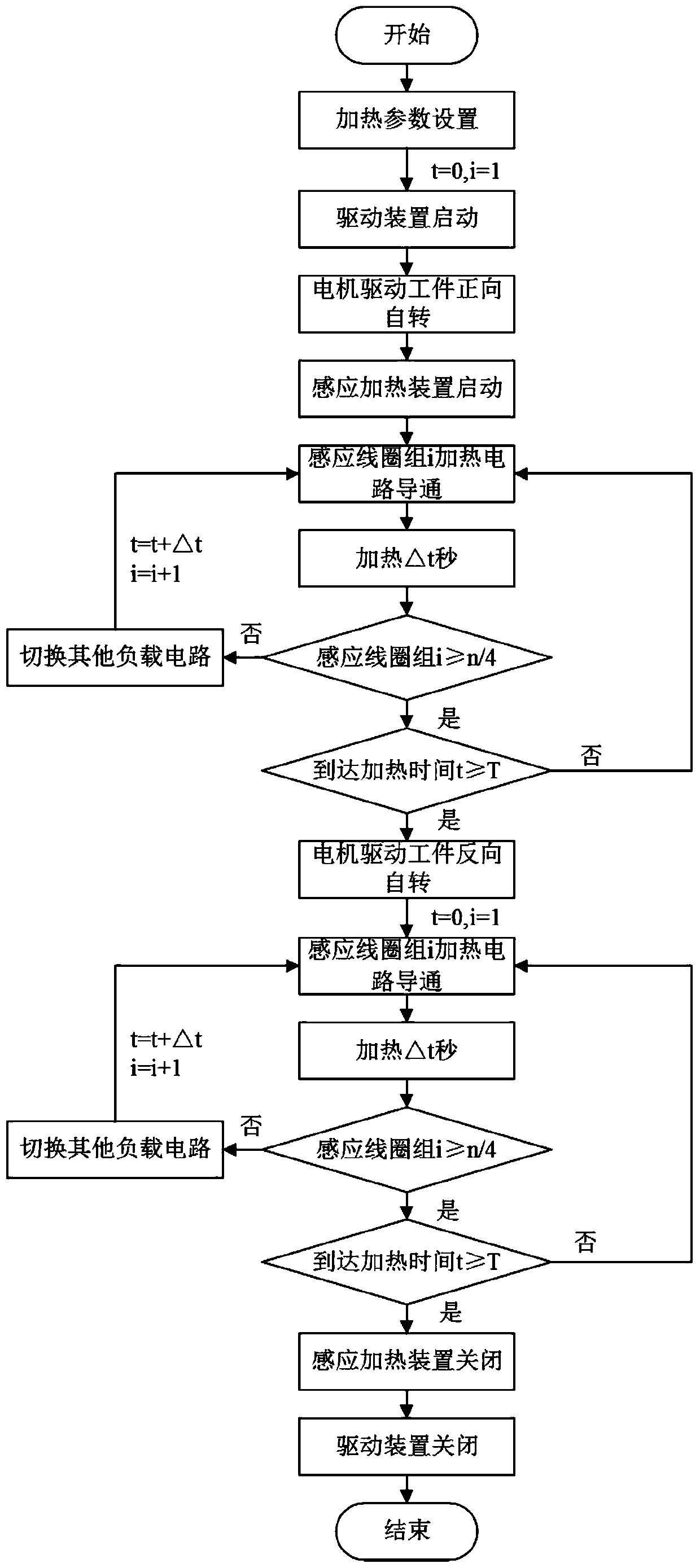
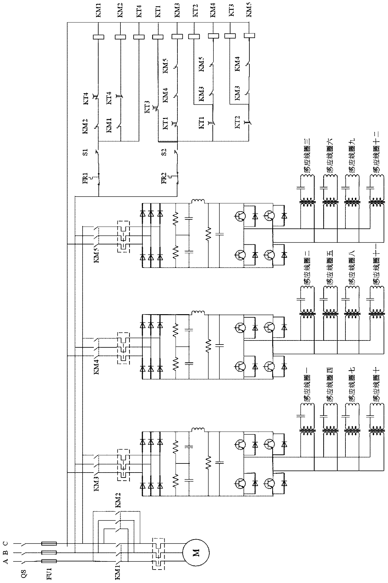
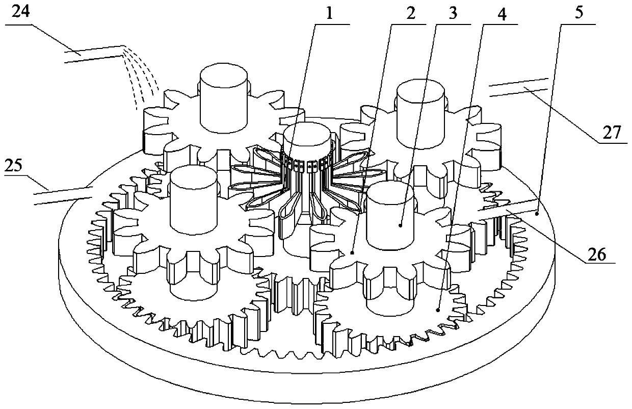
[0030] Such as Figure 3-5 As shown, the present invention discloses an induction heating device for gear surface quenching, which includes a heating gear shaft and a workpiece gear shaft that rotate in opposite directions, an induction heating gear 1 installed on the heating gear shaft, and an induction heating gear 1 installed on the workpiece gear shaft The gear workpiece 2 to be quenched on the surface; the induction heating gear 1 rotates coaxially with the heating gear shaft, and the gear workpiece 2 to be quenched rotates coaxially with the workpiece gear shaft; the induction heating gear 1 and the gear workpiece to be quenched 2 non-contact meshing; the teeth of the induction heating gear 1 are tooth-like induction coils.

[0031] Preferably, the heating gear shaft and the workpiece gear shaft are movably fixed on the base, the heating gear shaft is fixed with a ce...


PUM


Abstract

The invention discloses an induction heating device for gear surface quenching and a gear surface quenching method, and relates to the field of heat treatment. The induction heating device comprises aheating gear shaft and a workpiece gear shaft which are mutually and reversely rotated, an induction heating gear installed on the heating gear shaft, and a to-be-quenched gear workpiece installed onthe workpiece gear shaft. The induction heating gear is contactlessly meshed with the to-be-quenched gear workpiece in a non-contact mode. Teeth of the induction heating gear are a dentiform profileinduction coil. The induction heating device is capable of using the induction coil of which a shape is similar to a workpiece meshing gear to perform rotary-type scanning and heating on the workpiece, while the induction coil and the workpiece are simultaneously rotated, enabling a contact point of the workpiece and a positioning pulley on the induction coil to be always positioned in a meshing line, effectively heating a position in which load is applied to the workpiece, improving a heating depth, and increasing a thickness of a hardened layer of the position after water-cooling, thereby prolonging service life of the workpiece and reducing energy loss caused by uniform heating.

Description

technical field [0001] The invention relates to the field of heat treatment, in particular to an induction heating device for gear surface quenching and a gear surface quenching method. Background technique [0002] Heavy-duty precision gears are widely used in steel, building materials, petrochemical, paper, cement, coal, general machinery, wind power generation and other fields. After the gear fails, the installation and replacement costs are high, and surface fatigue wear is the main failure of heavy-duty gears. The method seriously affects the service life of the gear, so it is of great significance to reasonably control the quenching process of the gear. The surface quenching of gears by induction heating can use the skin effect to quickly heat the surface of the workpiece to the quenching temperature. For complex curved surfaces, it is difficult to effectively control the heating temperature distribution, so as to control the distribution of the effective hardened laye...

Claims


Application Information

Patent Timeline
Patent Type & Authority Patents(China)
IPC IPC(8): C21D1/10C21D1/667C21D9/32
CPCC21D1/10C21D1/667C21D9/0062C21D9/32Y02P10/25
Inventor 韩毅肖瑶
Owner 河北瑞丰科技有限公司
Learn More