
Large-current generator

A generator, high current technology, applied in the direction of electromechanical devices, electrical components, electric components, etc., can solve the problems of difficult disassembly of cooling fan blades, poor vibration damping effect of generators, and reduced service life, and achieves reliable assembly and installation. The effect of improving the shock absorption effect and prolonging the service life

Inactive Publication Date: 2018-12-28
广东井得电机股份有限公司
View PDF8 Cites 6 Cited by
  • Summary
  • Abstract
  • Description
  • Claims
  • Application Information

AI Technical Summary

Problems solved by technology

[0002] A generator refers to a mechanical device that converts other forms of energy into electrical energy. It is driven by a water turbine, steam turbine, diesel engine or other power machinery, and converts the energy generated by water flow, air flow, fuel combustion or nuclear fission into mechanical energy and transmits it to the generator. Then it is converted into electrical energy by a generator. Generators are widely used in industrial and agricultural production, national defense, science and technology, and daily life. The general principle of generator construction is to use appropriate magnetic and conductive materials to form a magnetic circuit for mutual electromagnetic induction. and circuits to generate electromagnetic power to achieve the purpose of energy conversion. The generators in the prior art have small output current and low power generation efficiency, which cannot meet people's needs. In addition, the cooling fan blades in the generator are not easy to disassemble and are inconvenient to maintain. , at the same time, the shock absorption effect of the generator is poor, and it is easy to cause damage to the generator after long-term use, so that its service life is reduced. Therefore, it is necessary to design a high-current generator

Method used


Image

  • Large-current generator
  • Large-current generator
  • Large-current generator

Examples


Embodiment Construction

[0029] The following will clearly and completely describe the technical solutions in the embodiments of the present invention with reference to the accompanying drawings in the embodiments of the present invention. Obviously, the described embodiments are only some, not all, embodiments of the present invention. Based on the embodiments of the present invention, all other embodiments obtained by persons of ordinary skill in the art without making creative efforts belong to the protection scope of the present invention.

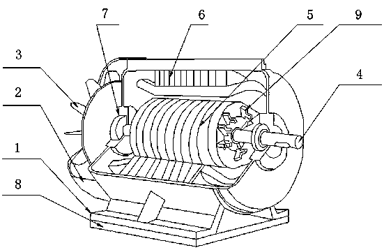
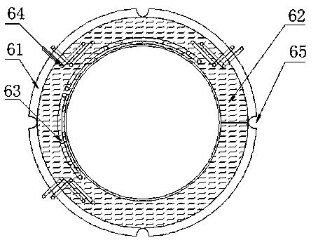
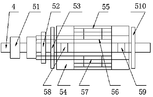
[0030] see Figure 1-6, the present invention provides a technical solution: a high-current generator, including a support base 1, a housing 2, a heat dissipation fan assembly 3, a rotating shaft 4, a rotor assembly 5, a stator assembly 6, a pulley 7, a base assembly 8 and a heat dissipation Fin 9, base assembly 8 is installed on the bottom of support seat 1, and base assembly 8 comprises support plate 81, support column 82, damping spring 83, push plate 84, d...


PUM


Abstract

A large current generator includes a support seat, a housing, a heat dissipation fan assembly, a rotating shaft, a rotor assembly, a stator assembly, a belt pulley, a base assembly and heat dissipation fins. The bottom of the support seat is provided with the base assembly, the base assembly includes a support plate, support columns, a damping spring, a push plate, a shock absorbing air bag, a support block, a first magnet, a second magnet and a seat, the bottom of the support seat is connected with the top of the support plate, the supporting columns are installed at the corresponding two ends of the bottom side of the support plate, a shock absorbing spring sleeves each support column, the bottom of each support column is connected with the top of the pushing plate, the bottom of the push plate is connected with the top of the shock absorbing airbag, and the bottom of the shock absorbing airbag is connected with the top of the support block. The generator has the advantages of largeoutput current, high power generation efficiency, easy disassembly of the cooling fan blades in the generator, convenient maintenance, good shock absorbing effect of the generator, and greatly prolonging the service life of the generator.

Description

technical field [0001] The invention relates to the technical field of generators, in particular to a high-current generator. Background technique [0002] A generator refers to a mechanical device that converts other forms of energy into electrical energy. It is driven by a water turbine, steam turbine, diesel engine or other power machinery, and converts the energy generated by water flow, air flow, fuel combustion or nuclear fission into mechanical energy and transmits it to the generator. Then it is converted into electrical energy by a generator. Generators are widely used in industrial and agricultural production, national defense, science and technology, and daily life. The general principle of generator construction is to use appropriate magnetic and conductive materials to form a magnetic circuit for mutual electromagnetic induction. and circuits to generate electromagnetic power to achieve the purpose of energy conversion. The generators in the prior art have small...

Claims


Application Information

Patent Timeline
IPC IPC(8): H02K5/24H02K9/06H02K3/46H02K1/28
CPCH02K1/28H02K3/46H02K5/24H02K9/06
Inventor 温舜彭志宏黄文锋
Owner 广东井得电机股份有限公司
Learn More