
Connecting rod type angle adjustable reflector for crooked road, and use method

A connecting rod type and reflector technology, applied in optics, optical components, installation, etc., can solve problems such as low installation efficiency, inconvenient adjustment and installation, and increased difficulty of road reflectors, so as to achieve strong applicability and avoid blown down by strong winds or blown crooked effect

Active Publication Date: 2018-12-28
孙骞
View PDF6 Cites 2 Cited by
  • Summary
  • Abstract
  • Description
  • Claims
  • Application Information

AI Technical Summary

Problems solved by technology

[0002] Road reflectors are widely used in road construction, and are generally installed on winding roads or places with sharp turns, so that drivers can observe the road conditions on the opposite curved road before turning and improve driving safety. However, road reflectors are installed and fixed. It is necessary to adjust the orientation and angle accordingly. The orientation and angle adjustment of traditional road reflectors are all done manually. The operation process is cumbersome and laborious, and the installation efficiency is low. At the same time, road maintenance or route changes When the road reflector needs to be adjusted twice, it will be more difficult, which will bring inconvenience to the adjustment and installation

Method used


Image

  • Connecting rod type angle adjustable reflector for crooked road, and use method
  • Connecting rod type angle adjustable reflector for crooked road, and use method

Examples


Embodiment Construction

[0023] The link-type angle-adjustable curved road reflector of the present invention and its method of use will be described in more detail below in conjunction with schematic diagrams, wherein a preferred embodiment of the present invention is shown, and it should be understood that those skilled in the art can modify the present invention described herein invention, while still realizing the beneficial effects of the present invention. Therefore, the following description should be understood as the broad knowledge of those skilled in the art, but not as a limitation of the present invention.

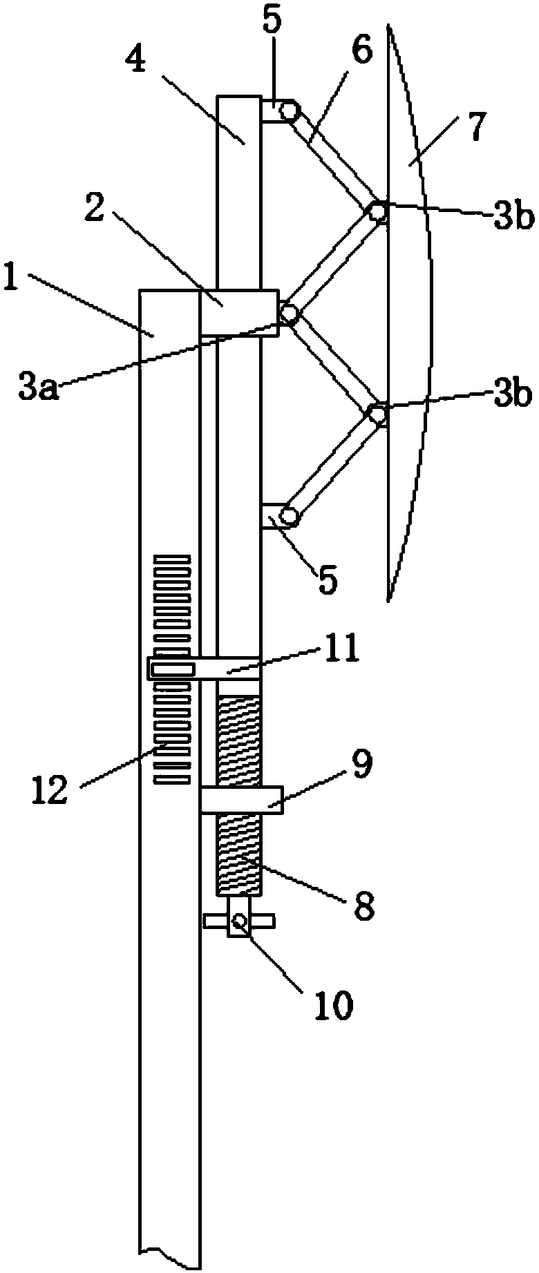
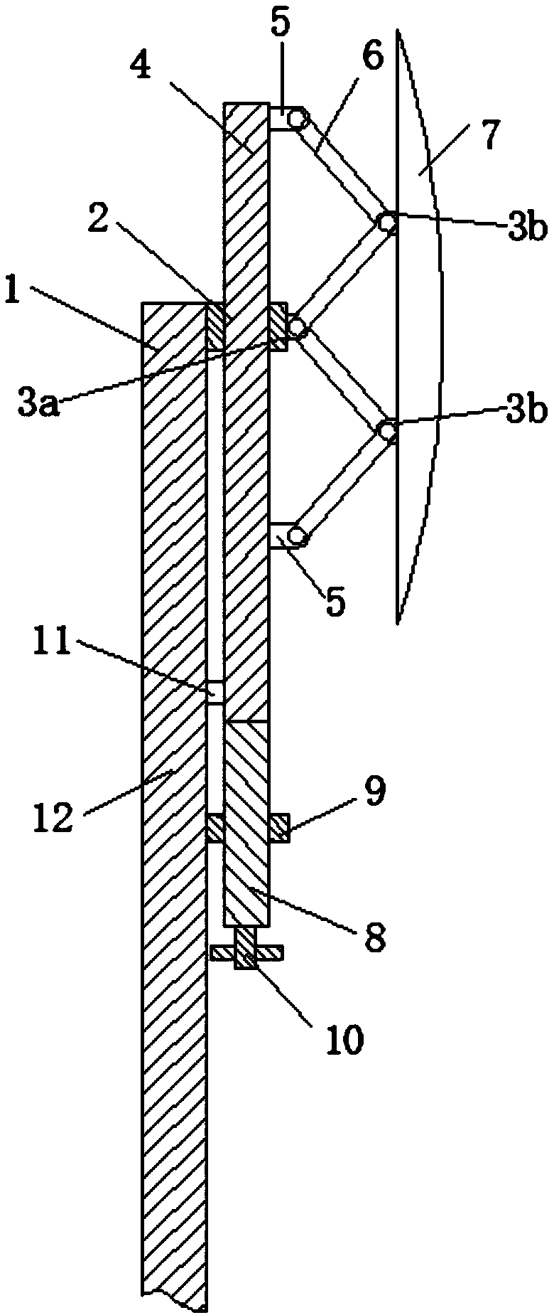
[0024] Such as figure 1 with figure 2 As shown, when the support rod 1 is installed at a predetermined position, if the pitch angle of the convex mirror 7 needs to be adjusted, it can be adjusted by turning the handle 10 .

[0025] The fixed plate 2 fixed on the support rod 1 is slidingly connected with the sliding rod 4, which is non-circular, such as any non-circular geometric sh...


PUM


Abstract

The invention provides a connecting rod type angle adjustable reflector for a crooked road. The connecting rod type angle adjustable reflector comprises a fixing plate fixed on a supporting rod, a sliding rod slidably arranged on the fixing plate in a penetration manner, a driving component for driving the sliding rod to move up and down parallel to the supporting rod, and a convex mirror, whereintwo transmission units are arranged between the sliding rod and the convex mirror, each transmission unit comprises a fixing boss and two connecting rods, the the fixing boss is fixedly connected toa back surface of the convex mirror, one ends of the two connecting rods are hinged to the fixing boss and are respectively located on both sides of the fixing boss, and the other ends of the two connecting rods are respectively hinged with the sliding rod and the fixing plate. The invention further provides a use method of the reflector. The driving component can drive the sliding rod to move upand down to adjust the angle of pitch of the convex mirror, meanwhile in cooperation with scales and a scaleplate, the scaleplate can mark the scales in real time for the reference of people, the settings can be conveniently adjusted during the installation, and a change can be conveniently made with the change of the road.

Description

technical field [0001] The invention relates to a reflector for detours, in particular to a link-type reflector for detours with adjustable angle and a use method thereof. Background technique [0002] Road reflectors are widely used in road construction, and are generally installed on winding roads or places with sharp turns, so that drivers can observe the road conditions on the opposite curved road before turning and improve driving safety. However, road reflectors are installed and fixed. It is necessary to adjust the orientation and angle accordingly. The orientation and angle adjustment of traditional road reflectors are all done manually. The operation process is cumbersome and laborious, and the installation efficiency is low. At the same time, road maintenance or route changes When the road reflector needs to be adjusted twice, the difficulty increases, which brings inconvenience to the adjustment and installation. Contents of the invention [0003] The object of...

Claims


Application Information

Patent Timeline
Patent Type & Authority Applications(China)
IPC IPC(8): G02B7/182
CPCG02B7/1821
Inventor 孙骞
Owner 孙骞
Learn More