
Multi-heat source waste heat recovery system

A waste heat recovery system and multi-heat source technology, applied in the direction of heat exchangers, heat exchanger types, indirect heat exchangers, etc., can solve the problems of huge size, affecting the effect of waste heat utilization, and many recovery equipment, so as to save energy and improve comprehensive Use efficiency to realize the effect of self-production and self-sale

Active Publication Date: 2018-12-28
SOUTHEAST UNIV
View PDF9 Cites 2 Cited by
  • Summary
  • Abstract
  • Description
  • Claims
  • Application Information

AI Technical Summary

Problems solved by technology

According to the current waste heat recovery technology, most of the high-temperature waste heat can be recycled according to the waste heat temperature range, but a large number of low-temperature waste heat resources have not been fully recovered and utilized due to low energy quality, and one device can only recover one kind of waste heat source. To recycle waste heat resources in different temperature ranges, different recovery equipment is required. There are many recovery equipments and the system is complex and huge; waste heat resources are affected by the production process, and have the disadvantages of intermittent and unstable. In the process of using waste heat for production and life The instability of medium waste heat resources will affect the effect of waste heat utilization, and the practicability and sense of use are poor

Method used


Image

  • Multi-heat source waste heat recovery system

Examples


Embodiment Construction

[0016] The present invention will be further described below in conjunction with accompanying drawing.

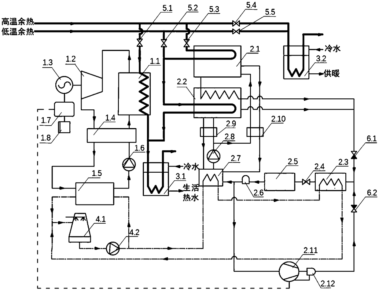
[0017] like figure 1 As shown, a multi-heat source waste heat recovery system of the present invention includes a power generation system, a refrigeration system, a heating system and a cooling system.

[0018] Power generation system: including sequentially connected evaporator I1.1, turbine 1.2, regenerator 1.4, condenser I1.5, working medium pump 1.6, turbine 1.2 is connected to generator 1.3, generator 1.3 is connected to controller 1.7, The controller 1.7 is connected to the battery 1.8 and the compressor 2.11, the condenser I1.5 is connected to the cooling system, and the evaporator I1.1 is connected to the low-temperature water storage tank 3.1 of the heating system. The evaporator I1.1 is connected to the high-temperature waste heat through the valve I5.1.

[0019] The internal circulating working medium of the power generation system is an organic working medium,...


PUM


Abstract

The invention relates to a multi-heat source waste heat recovery system which includes a power generation system, a refrigeration system, a heating system and a cooling system; the power generation system is used for providing electric energy for the refrigeration system, the refrigeration system uses high temperature waste heat and low temperature waste heat for refrigeration, the waste heat usedby the power generation system and the refrigeration system is used for the heat source cascade of the heating system, and the cooling system is used for cooling a power supply system and the refrigeration system. According to the multi-heat source waste heat recovery system, different waste heat recovery modes are adopted according to different residual heat source temperatures, the high temperature waste heat is used for the power generation system, and the generated electric energy can drive the compression refrigeration system to cool; the cooling system can recycle high temperature wasteheat and low temperature waste heat at the same time, and the waste heat after cooling can enter the low temperature water tank to provide hot water for daily life, so as to realize waste heat recovery with high quality and cascade utilization, and the internal energy can be transformed and utilized mutually, thus improving the comprehensive utilization efficiency of energy.

Description

technical field [0001] The invention relates to the technical field of energy recovery, in particular to a multi-heat source waste heat recovery system. Background technique [0002] Industrial buildings have abundant waste heat resources, which are characterized by various types, wide temperature ranges, and instability. According to the current waste heat recovery technology, most of the high-temperature waste heat can be recycled according to the waste heat temperature range, but a large number of low-temperature waste heat resources have not been fully recovered and utilized due to low energy quality, and one device can only recover one kind of waste heat source. To recycle waste heat resources in different temperature ranges, different recovery equipment is required. There are many recovery equipments and the system is complex and huge; waste heat resources are affected by the production process and have the disadvantages of intermittent and unstable. In the process of ...

Claims


Application Information

Patent Timeline
IPC IPC(8): F28D21/00
CPCF28D21/0001
Inventor 蔡亮陈丽萍张潇徐啸乔静宜
Owner SOUTHEAST UNIV
Learn More