An optical fiber light emitting structure, manufacturing device and manufacturing method thereof

A light-emitting structure and optical fiber technology, which is applied to lighting devices, lighting device light guides, lighting device components, etc., can solve the problems of lack of fiber optic cable wiring, single fiber wiring structure, waste of fiber light sources, etc., and achieve uniform light and wiring. Clear, Efficient Effects

Inactive Publication Date: 2018-12-28
黄利军
View PDF5 Cites 1 Cited by
  • Summary
  • Abstract
  • Description
  • Claims
  • Application Information

AI Technical Summary

Problems solved by technology

[0003] In order to solve the technical vacancies in the current field of optical fiber that lack optical fiber cable wiring, the present invention solves the problems of single optical fiber wiring structure, waste of some optical fiber light sources, and non-uniform defects in the light derived from the side of the optical fiber, and provides an optical fiber wiring structure and its Wiring method

Method used


Image

  • An optical fiber light emitting structure, manufacturing device and manufacturing method thereof
  • An optical fiber light emitting structure, manufacturing device and manufacturing method thereof
  • An optical fiber light emitting structure, manufacturing device and manufacturing method thereof

Examples


Embodiment 1

[0031] In order to make the technical means, creative features, goals and effects of the present invention easier to understand, the present invention will be further described below in conjunction with specific embodiments.

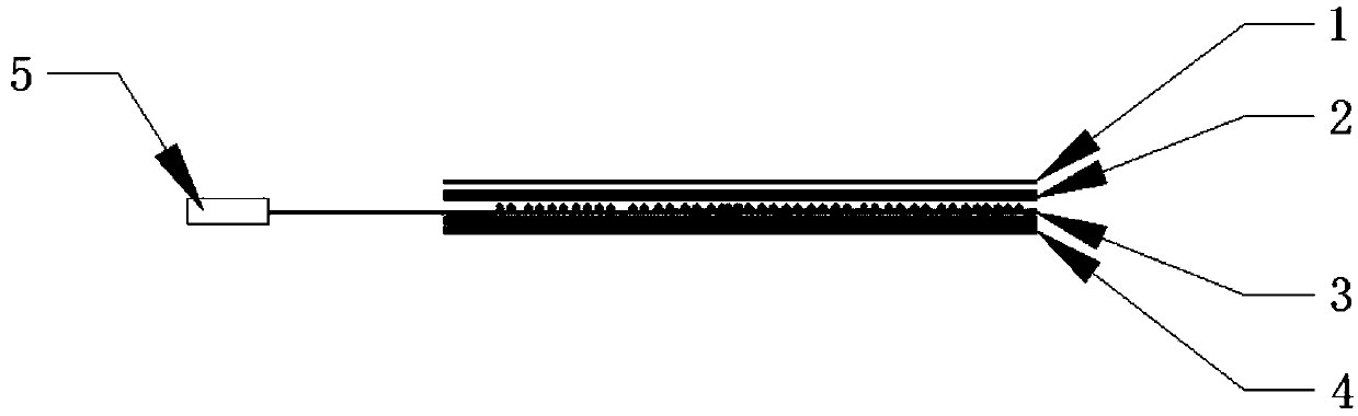
[0032] An optical fiber light-emitting structure, comprising a reflective sheet 4, an optical fiber layer 3 arranged on the reflective sheet 4, a diffusion sheet 1 arranged on the optical fiber layer 3, and a light source 5 connected to the optical fiber layer 3; the optical fiber layer 3 is a guide Composition of optical fibers.

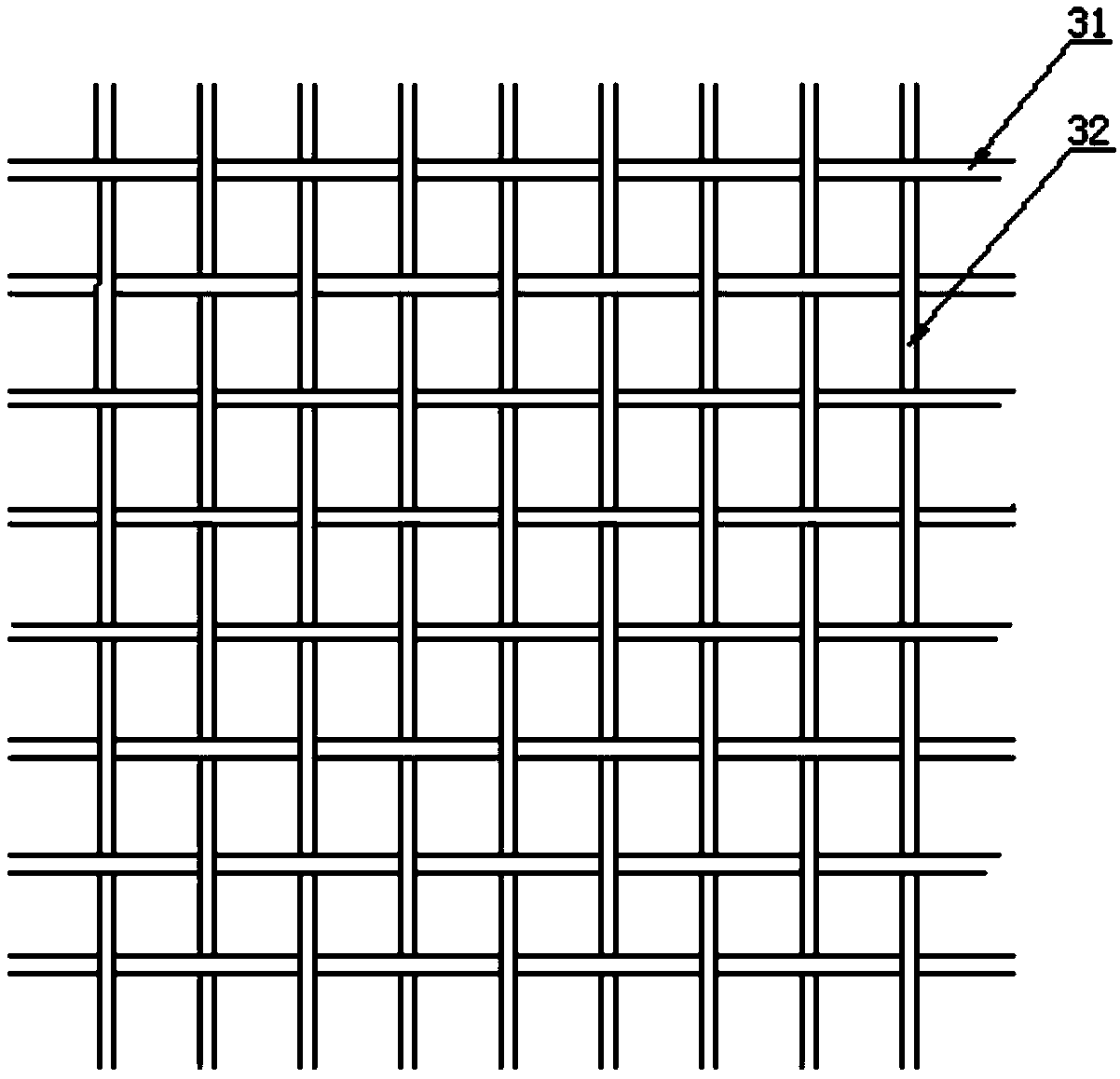
[0033] Specifically, the arrangement of the light-guiding optical fibers in the optical fiber layer 3 is further optimized, that is, transverse optical fibers 31 and longitudinal optical fibers 32 are planned, and the transverse optical fibers 31 are parallel to each other, similarly, the longitudinal optical fibers 32 parallel to each other.

[0034] Wherein, the number of optical fiber bundles and the number of optical fibe...

Embodiment 2

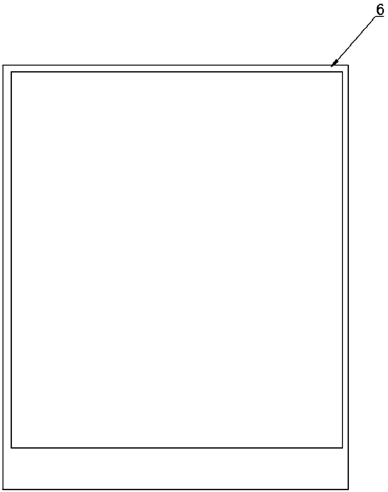
[0041] This embodiment is a manufacturing device and manufacturing method of an optical fiber light-emitting structure in Embodiment 1; specifically, the manufacturing device is an optical fiber braided frame 6, such as image 3 As shown, it includes an upper frame 61 and a lower frame 62; the upper frame 61 is connected to the bottom edge of the lower frame 62 and forms an angle α between the upper frame 61 and the lower frame 62, and the angle α is 10-30°, specifically, its side is as Figure 4 shown.

[0042] Further, a manufacturing method of an optical fiber light-emitting structure based on the optical fiber braided frame 6 includes the following steps:

[0043] (1) take the optical fiber braiding frame 6 and some optical fibers for use;

[0044] (2) Take some optical fibers from the angle α formed by the upper frame 61 and the lower frame 62 and insert them into the light weaving frame 6 in parallel longitudinally, so that the optical fibers are positioned above the f...


PUM


Abstract

The invention discloses a fiber-optic wiring structure comprising a reflector plate (4), the optical fiber layer (3) disposed on the reflector plate (4), and a diffuser film (1) disposed on the optical fiber layer (3) and a light source (5) connected to the optical fiber layer (3). The optical fiber layer (3) comprises a transverse optical fiber (31), a longitudinal optical fiber (32), a right-leaning fiber bundle (33), and a left-tilted fiber bundle (34), which are alternately woven in an intersective arrangement to a network structure. The invention also discloses a wiring method based on this wiring structure. The invention makes the light guiding ray of the optical fiber brighter and the wiring clear, the efficiency of the light guiding backlight of the optical fiber is improved and the light derived from the side is more uniform.

Description

technical field [0001] The invention relates to the field of optical fiber light guiding backlight, in particular to an optical fiber light-emitting structure, a manufacturing device and a manufacturing method thereof. Background technique [0002] With the development of science and technology, the application of optical fiber is more and more extensive. In recent years, the technical means of guiding light from the side of the optical fiber has appeared, and the technical breakthrough of optical fiber light guide has been realized. On this basis, it has derived including optical fiber Invention of light guide lighting system, backlight module and other technologies. However, due to the physical properties of optical fibers that are easy to break and break, there is no optical fiber wiring method in the prior art, so the optical fiber wiring structure is disordered and relatively simple, and there are multiple optical fibers that emit light overlapping, resulting in optical...

Claims


Application Information

Patent Timeline
Patent Type & Authority Applications(China)
IPC IPC(8): F21S2/00F21V8/00F21V7/05F21V5/08
CPCF21S2/00F21V5/08F21V7/05F21V2200/15
Inventor 黄利军李娜
Owner 黄利军
Why Eureka
Try Eureka