
Natural gas engine combustion organization method with precombustion chamber low-pressure air supply and in-cylinder high-pressure direct injection functions

A technology of pre-combustion chamber and natural gas, applied in gaseous engine fuel, combustion engine, internal combustion piston engine, etc., to achieve the effects of accelerating flame propagation speed, improving economy and emission, and shortening combustion time

Active Publication Date: 2018-12-28
HARBIN ENG UNIV
View PDF13 Cites 13 Cited by
  • Summary
  • Abstract
  • Description
  • Claims
  • Application Information

AI Technical Summary

Problems solved by technology

However, these patents did not conduct detailed studies on the formation of the mixture in the pre-chamber and the main combustion chamber, the rational organization of combustion, and the stable propagation of the flame in the pre-chamber to the main combustion chamber.

Method used


Image

  • Natural gas engine combustion organization method with precombustion chamber low-pressure air supply and in-cylinder high-pressure direct injection functions
  • Natural gas engine combustion organization method with precombustion chamber low-pressure air supply and in-cylinder high-pressure direct injection functions
  • Natural gas engine combustion organization method with precombustion chamber low-pressure air supply and in-cylinder high-pressure direct injection functions

Examples


Embodiment Construction

[0019] The present invention is described in more detail below in conjunction with accompanying drawing example:

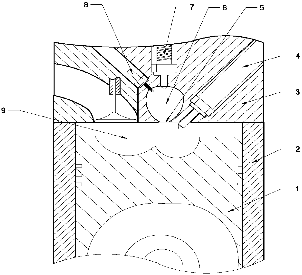
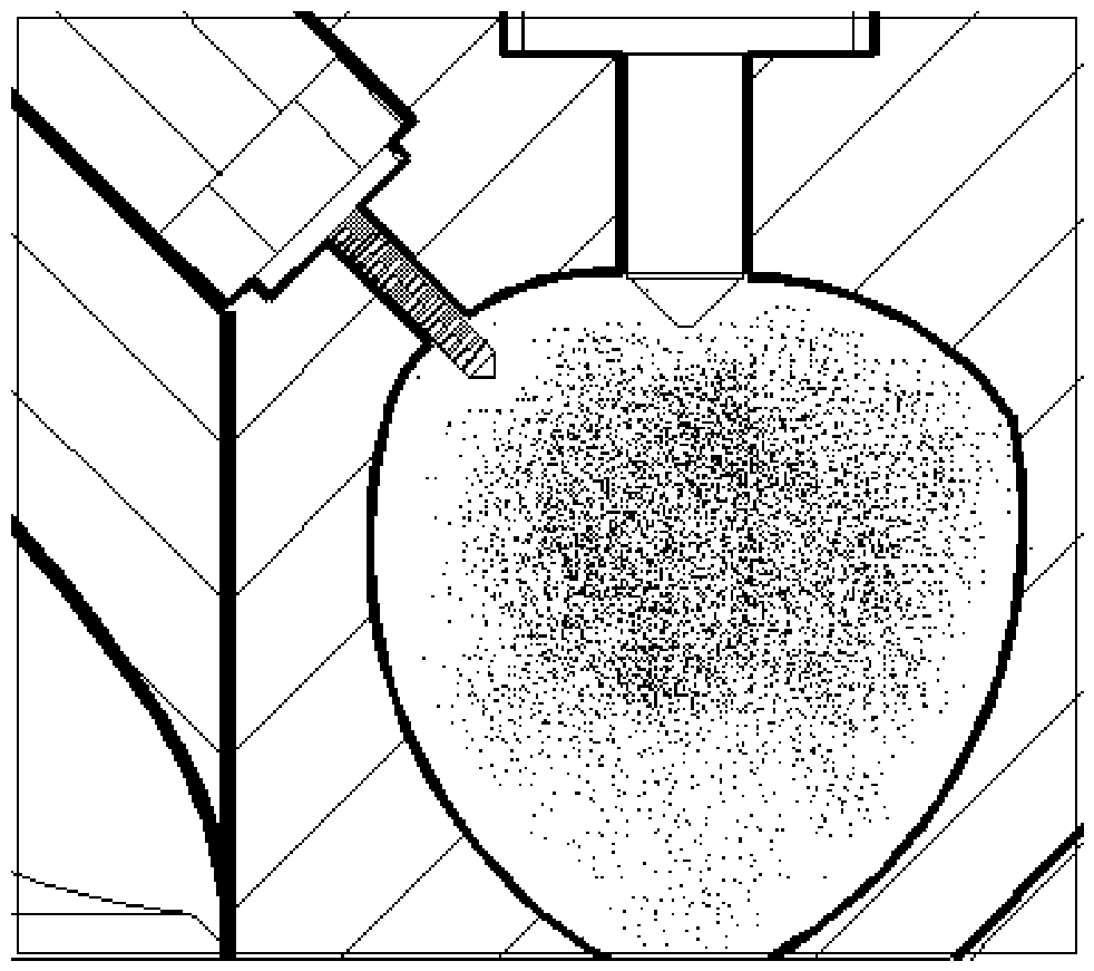
[0020] combine Figure 1-4 , the structure of the natural gas engine combustion system of the present invention includes: piston 1, cylinder liner 2, cylinder head 3, high-pressure gas injection device 4, pre-combustion chamber outlet 5, pre-combustion chamber 6, low-pressure one-way gas supply device 7, spark plug 8, main Combustion chamber9. The ω-shaped main combustion chamber is composed of the upper surface of the piston, the peripheral wall of the cylinder liner and the lower surface of the cylinder head. The lower narrow oval structure, the central axis of the pre-combustion chamber coincides with the central axis of the cylinder, the outlet of the pre-chamber is located at the center of the bottom of the pre-chamber, the diameter of the outlet is not less than 5mm, and the maximum diameter of the oval pre-chamber is equal to the diameter of the outlet of ...


PUM


Abstract

The invention aims to provide a natural gas engine combustion organization method with precombustion chamber low-pressure air supply and in-cylinder high-pressure direct injection functions. The natural gas engine combustion organization method is characterized in that a high-pressure gas injecting device is mounted on a cylinder cover, and gas injected at the tail end of compression stroke formsconcentration gradient distribution in a cylinder; a precombustion chamber is positioned right above a main combustion chamber, and a sparking plug is obliquely mounted on the left above the precombustion chamber; a low-pressure one-way air supply valve is mounted at the top of the precombustion chamber and is used for supplying air into the precombustion chamber during the intake stroke, such airand air pushed into the precombustion chamber during the compression stroke form a combustible gas mixture, the combustible gas mixture is ignited by the sparking plug, and flames enter a gas mixturein an ignition cylinder of the main combustion chamber; the air supply pressure of the one-way air supply valve is controlled at 4-6 bar during a low load and at 8-10 bar during a high load. The natural gas engine combustion organization method has the advantages that the ignition stability in different operation conditions can be guaranteed through adjustment of the air supply pressure in the one-way valve, and concentration stratification and rapid combustion of the thin gas mixture in the cylinder are achieved through in-cylinder direct injection, so that an engine is more economical and higher in exhaust performance.

Description

technical field [0001] The invention relates to a combustion control method, in particular to a natural gas engine combustion control method. Background technique [0002] Natural gas is a green fuel with abundant reserves and clean emissions. Using it as a substitute fuel for petroleum in the engine field can effectively improve the current plight of energy shortage and environmental pollution. [0003] Natural gas engines can be divided into gas supply outside the cylinder and gas supply inside the cylinder according to the gas supply method. The gas supply method outside the cylinder is divided into single-point intake in the intake manifold and multi-point intake in the intake manifold. The single-point intake method will not work Avoiding a large amount of natural gas escaping will not only cause a large amount of hydrocarbon emissions, but also is not conducive to improving fuel economy. Although the multi-point intake method can reduce natural gas escape, this method ...

Claims


Application Information

Patent Timeline
IPC IPC(8): F02B19/10F02B43/00F02D19/02
CPCF02B19/1019F02B19/108F02B43/00F02D19/02Y02T10/12Y02T10/30
Inventor 杨立平何永恒范立云宋恩哲姚崇孙军
Owner HARBIN ENG UNIV
Learn More