
Basket lifting deoiling assembly, vacuum frying tank and vacuum frying equipment

A technology of vacuum frying tanks and baskets, which is applied in the direction of oil/fat baking, etc., can solve the problems of increasing the cost of vacuum frying equipment, prolonging food production time, and low food processing efficiency, so as to improve food processing efficiency and food processing The effect of shortening the time and reducing the processing and manufacturing costs

Pending Publication Date: 2018-12-28
全氏食品机械(上海)有限公司
View PDF10 Cites 2 Cited by
  • Summary
  • Abstract
  • Description
  • Claims
  • Application Information

AI Technical Summary

Problems solved by technology

[0003] However, the existing vacuum frying equipment has the following disadvantages: after frying the food raw materials in the basket, the edible oil in the tank needs to be extracted first, and the finished food can be obtained by vacuuming again for deoiling. When a batch of food needs to be re-injected into the tank, heated and vacuumized, on the one hand, the production time of the food is prolonged, resulting in low food processing efficiency; on the other hand, an external oil storage tank is required for temporary storage from the tank Extracted cooking oil, which increases the cost of vacuum frying equipment
In addition, re-vacuuming is required before deoiling and reheating and vacuuming are required after oil filling, resulting in a lot of energy waste

Method used


Image

  • Basket lifting deoiling assembly, vacuum frying tank and vacuum frying equipment
  • Basket lifting deoiling assembly, vacuum frying tank and vacuum frying equipment
  • Basket lifting deoiling assembly, vacuum frying tank and vacuum frying equipment

Examples


Deformed example 2

[0086] This modification is a modification of the embodiment and the first modification. In the following description, the same reference numerals are assigned to the same structures as those in the first embodiment and the first modification, and the same descriptions are omitted.

[0087] The difference between this modified example and the first modified example is that the number of support columns 33c in the basket frame 33 is two, and correspondingly, the number of upper frame arms 33d and lower frame arms 33f are both three.

[0088] Compared with the first embodiment and the first modification, because the number of support columns, upper frame arms and lower frame arms is relatively small, it is possible to ensure that the material basket can be fixed in the material basket frame and the material basket is easy to be taken and placed. Basically, the structure of the basket frame is simpler and the manufacturing cost is lower.

Deformed example 3

[0090] This modification is a modification of the embodiment, the first modification and the second modification. In the following description, the same reference numerals are assigned to the same structures as those in the embodiment, the first modification, and the second modification, and the same descriptions will be omitted.

[0091] The difference between this modified example and the embodiment, modified example 1 and modified example 2 lies in that: the rotating shaft of the material basket and the axial mounting hole are different in structure to achieve circumferential fixing and axial lifting.

[0092] In this modified example, the basket rotating shaft 43 is provided with groove pins (not shown) along the axial direction of the basket rotating shaft 43, and the wall of the axial mounting hole 41d is provided with a pin along the axial direction of the mounting hole 41d. A guide groove (not shown) in the axial direction and matched with the groove pin, the groove pi...


PUM


Abstract

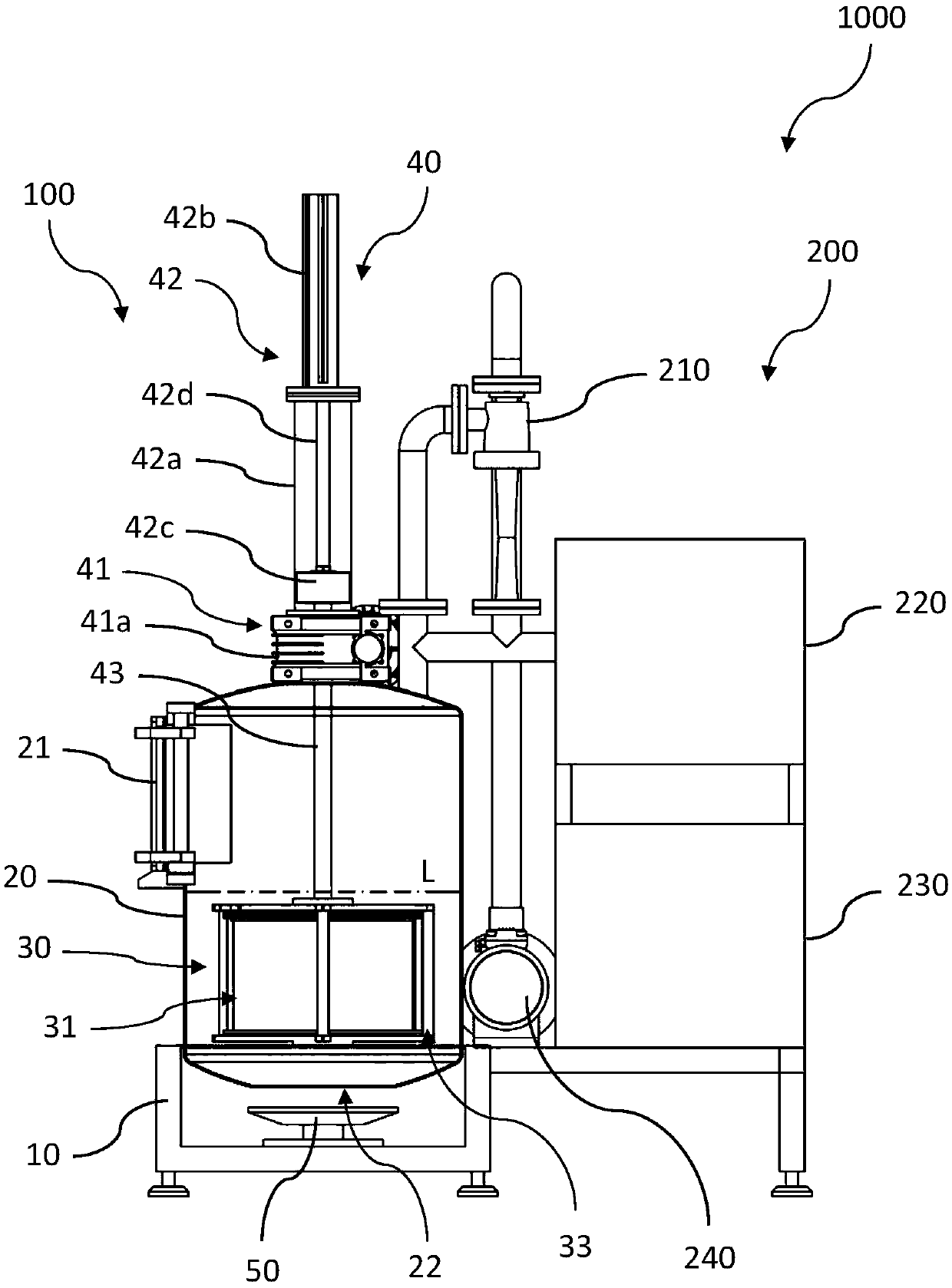
The invention provides a basket lifting deoiling assembly, a vacuum frying tank containing the basket lifting deoiling assembly, and vacuum frying equipment containing the vacuum frying tank. The basket lifting deoiling assembly comprises a rotary unit, a lifting unit, and a basket rotary shaft, wherein the rotary unit comprises a speed reducer and a rotary driving component; the lifting unit hasa supporting sleeve and a lifting driving component; the lower end of the basket rotary shaft is connected with a basket component; an output shaft is arranged on the speed reducer; an axial mountinghole is formed in the output shaft; the free end of each a driving rod of the lifting driving component extends downwards into the supporting sleeve; the upper end of the basket rotary shaft penetrates through the axial mounting hole and is connected with the free end of each the driving rod along an axial fixed circumferential direction in a rotary manner; and the basket rotary shaft is mounted in the axial mounting hole along a circumferential fixed axial direction in a lifting manner. When the lifting driving component drives the basket assembly to complete the lifting action, the rotary driving component drives the basket assembly to rotate to realize deoiling.

Description

technical field [0001] The invention belongs to the technical field of food processing equipment, and in particular relates to a basket lifting and deoiling assembly, a vacuum frying tank comprising the basket lifting and deoiling assembly, and vacuum frying equipment comprising the vacuum frying tank. Background technique [0002] Vacuum frying equipment is widely used in various food factories, fast food restaurants, fried chicken shops and pastry shops because of its good flavor and taste. [0003] However, the existing vacuum frying equipment has the following disadvantages: after frying the food raw materials in the basket, the edible oil in the tank needs to be extracted first, and the finished food can be obtained by vacuuming again for deoiling. When a batch of food needs to be re-injected into the tank, heated and vacuumized, on the one hand, the production time of the food is prolonged, resulting in low food processing efficiency; on the other hand, an external oil...

Claims


Application Information

Patent Timeline
Patent Type & Authority Applications(China)
IPC IPC(8): A21B5/08
CPCA21B5/08
Inventor 全武
Owner 全氏食品机械(上海)有限公司
Learn More