
Novel non-contact electromagnetic acoustic emission signal excitation experimental device

A signal-transmitting, non-contact technology used in material analysis, instrumentation, and material analysis using acoustic wave emission technology. The transmission signal is stable and reliable, the signal analysis function is rich, and the system is easy to build.

Inactive Publication Date: 2018-12-25
CHONGQING THREE GORGES UNIV
View PDF7 Cites 4 Cited by
  • Summary
  • Abstract
  • Description
  • Claims
  • Application Information

AI Technical Summary

Problems solved by technology

However, the load will cause irreversible damage to the tested specimen, and there are still great difficulties in applying stress to the entirety of large components
At the same time, during the propagation of the acoustic emission signal, the signal is distorted due to the noise interference signal integrated into the stress-loaded equipment, and the continuous scattering and reflection of the signal at the material boundary, thereby reducing the true reliability of the signal.
This leads to problems such as low reliability, poor stability, and damage to the measured material of the collected signal.
[0003] To sum up, the problems existing in the existing technology are: the current acoustic emission signal acquisition method used in defect detection has low reliability, poor stability, contact with the tested material, and damage to the tested material.
[0004] Metal materials have the advantages of high tensile strength, corrosion resistance, and good welding performance, so they are widely used in all walks of life. Due to the imprecise or negligent production process, it is likely to cause tiny defects, cracks, and even some defective materials inside the material. The external and complete materials are the same, and various metal structures are becoming more and more complex and large, making it impossible for us to directly identify defects with the naked eye, which makes it difficult to detect complex structural defects

Method used


Image

  • Novel non-contact electromagnetic acoustic emission signal excitation experimental device
  • Novel non-contact electromagnetic acoustic emission signal excitation experimental device
  • Novel non-contact electromagnetic acoustic emission signal excitation experimental device

Examples


Embodiment Construction

[0030] In order to further understand the content, features and effects of the present invention, the following examples are given, and detailed descriptions are given below with reference to the accompanying drawings.

[0031] The structure of the present invention will be described in detail below in conjunction with the accompanying drawings.

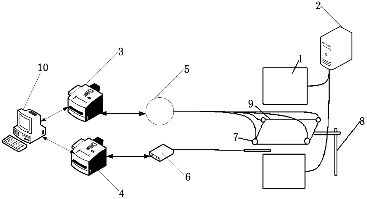
[0032] like figure 1 As shown, the experimental device for the excitation of the novel non-contact electromagnetic acoustic emission signal provided by the embodiment of the present invention, the experimental device for the excitation of the novel non-contact electromagnetic acoustic emission signal includes:

[0033] For data analysis, operation signal processing module 10;

[0034] Connected with the signal processing module 10, it is used to detect the acoustic emission signal acquisition system 3 of the weak electromagnetic acoustic emission signal;

[0035] Connected with the signal processing module 10, for detecting the gau...


PUM


Abstract

The invention belongs to the technical field of nondestructive testing, and discloses a novel non-contact electromagnetic acoustic emission signal excitation experimental device. The novel non-contactelectromagnetic acoustic emission signal excitation experimental device is provided with a signal processing module used for data analysis and calculation, an acoustic emission signal acquisition system connected with the signal processing module and used for detecting weak electromagnetic acoustic emission signals and a gauss meter connected with the signal processing module and used for detecting magnetic field intensity. The acoustic emission signal acquisition system is connected to sensors fixed to the four corners of a conductive defect material plate by an amplifier, the gauss meter isconnected with a hall probe which is arranged between a group of parallel corresponding electromagnets, and the electromagnets are connected with a program-controlled current source through a wire. The problems of low reliability, poor stability, contact with a material to be detected, damage to the material to be detected and other shortcomings of an acoustic emission signal acquisition method currently used for defect detection are solved.

Description

technical field [0001] The invention belongs to the technical field of non-destructive testing, and in particular relates to a novel non-contact electromagnetic acoustic emission signal excitation experimental device. Background technique [0002] At present, metal alloy materials are widely used in construction, aviation, railway, automobile, subway and many other industries because of their high tensile strength, good fatigue strength, excellent welding characteristics, good wear resistance, corrosion resistance, and many other advantages. middle. In modern society, various metal structures are becoming more and more complex and large-scale, and any small defect in any component will have an incalculable impact on the entire structure, so it is necessary for the performance of various workpieces to meet higher safety standards. Therefore, before various metal structures are officially used, it is very necessary to detect defects through technical means. When the electrom...

Claims


Application Information

Patent Timeline
Patent Type & Authority Applications(China)
IPC IPC(8): G01N29/14
CPCG01N29/14G01N2291/0234
Inventor 赖于树熊燕刘琪崔俊
Owner CHONGQING THREE GORGES UNIV
Learn More