
Hub-motor-driven convey device and conveying system, and convey method

A technology for in-wheel motors and handling devices, which is applied in power units, motor vehicles, transportation and packaging, etc., can solve the problems of inability to achieve 360° steering on the spot, inconvenient turning and steering, and insufficient flexibility of trucks. Improve work efficiency, simple structure, and reduce the effect of manual intervention

Active Publication Date: 2018-12-25
SHANDONG INST OF ADVANCED TECH CHINESE ACAD OF SCI CO LTD
View PDF7 Cites 15 Cited by
  • Summary
  • Abstract
  • Description
  • Claims
  • Application Information

AI Technical Summary

Problems solved by technology

[0005] 1. The existing handling AGV must rely on ground magnetic strip navigation to operate, and cannot operate in areas without magnetic strips. It is restricted in many occasions and the utilization rate of equipment is low.
[0006] 2. The existing fuel handling forklifts and other handling tools are costly, noisy, and emit harmful gases, and each handling forklift needs to be equipped with an operator, which is expensive to use
[0007] 3. The existing trucks are not flexible enough to turn 360° on the spot. It is inconvenient to turn around and turn, and cannot adapt to work in a narrow working area.

Method used


Image

  • Hub-motor-driven convey device and conveying system, and convey method
  • Hub-motor-driven convey device and conveying system, and convey method
  • Hub-motor-driven convey device and conveying system, and convey method

Examples


Embodiment Construction

[0049] In order to make the objectives, technical solutions and advantages of the present invention clearer, the following further describes the present invention in detail with reference to the accompanying drawings and embodiments. It should be understood that the specific embodiments described herein are only used to explain the present invention, but not to limit the present invention.

[0050] It should be noted that the terms "setting", "connection", "docking", "electrical connection", etc. should be understood in a broad sense, for example, they can be directly set, connected, docked, and electrically connected, or they can be centered The structure is set up, connected, docked, and electrically connected indirectly.

[0051] In addition, if there are "vertical", "horizontal", "length", "width", "thickness", "upper", "lower", "front", "rear", "left" and " The terms “right”, “vertical”, “horizontal”, “top”, “bottom”, “inner” and “outer” indicate the orientation or positional...


PUM


Abstract

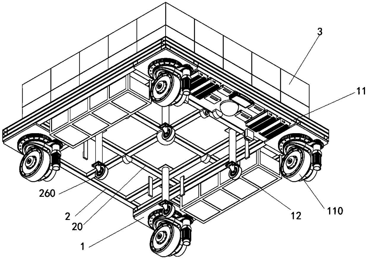
The invention is applicable to the technical field of new energy vehicles and ground transportation equipment, and discloses a conveying device and a conveying system driven by a hub motor, and a conveying method. The transporting device comprises a transporting truck which can be used for locking and driving with a truck, and the transporting truck comprises a transporting truck frame which is connected with an energy storage device, a steering device, an alignment device, a transporting truck docking locking device, a transporting truck positioning device, a driving wheel driven by a hub motor, and a whole truck controller which can plan a moving path or receive a moving path. The transporting truck frame is connected with an energy storage device, a steering device, an alignment device,a transporting truck docking locking device, and a transporting truck positioning device. The handling system comprises the handling device and the dispatching control center. The conveying method uses the conveying device and the conveying system. The invention provides a conveying device and a conveying system driven by a wheel hub motor, and a conveying method thereof. The conveying device hashigh equipment utilization ratio, and the conveying vehicle can be flexibly turned in a narrow space and can realize multi-purpose of one vehicle, so that the conveying device can replace manual conveying, save energy and environmental protection, and has high efficiency and low cost.

Description

Technical field [0001] The invention belongs to the technical field of new energy vehicles and ground transportation equipment, and particularly relates to a transportation device, a transportation system and a transportation method based on a hub motor drive. Background technique [0002] Warehouse freight is a link that any factory or warehousing logistics company must face. Especially now that the cost of land use by enterprises is getting higher and higher, the requirements for the space utilization rate of warehousing are naturally higher and higher. Various operations such as stacking and transshipment of large-sized goods require low manual handling efficiency, and it is difficult to ensure the safety of workers. Traditional gas-turbine-type goods transport vehicles are expensive, noisy, emit harmful gases, have poor flexibility, and are not suitable for small working areas. [0003] With the development of society and economy and the progress of science and technology, in t...

Claims


Application Information

Patent Timeline
IPC IPC(8): B60K7/00B62D5/04G05B19/418G05D1/02
CPCG05D1/0223G05D1/0225G05D1/0236G05D1/0274G05B19/41865G05B19/41895B62D5/0418B60K7/0007Y02P90/02
Inventor 刘小青潘仲鸣李程宇贾慧波
Owner SHANDONG INST OF ADVANCED TECH CHINESE ACAD OF SCI CO LTD
Learn More