
Wastewater Treatment Method Using Membrane Separation Activated Sludge Process

A technology of activated sludge method and wastewater treatment, which is applied in water/sludge/sewage treatment, sludge treatment, biological water/sewage treatment, etc. It can solve the problems of deterioration of filtration, prolongation of chemical liquid impregnation time, and complexity. Achieving the effect of reducing the risk of adverse effects

Active Publication Date: 2021-09-07
TORAY IND INC
View PDF16 Cites 0 Cited by
  • Summary
  • Abstract
  • Description
  • Claims
  • Application Information

AI Technical Summary

Problems solved by technology

[0007] However, once the sludge is firmly or heavily attached to the membrane surface, sometimes it can only partially recover even with chemical liquid cleaning.
In the case of increasing the concentration of the chemical liquid and prolonging the immersion time of the chemical liquid in order to improve the cleaning effect, there is a problem that part of the injected chemical liquid flows out into the tank during cleaning, resulting in a decrease in the physiological activity of microorganisms in the activated sludge , Decompose the sludge and deteriorate the filterability and other adverse effects
On the other hand, there is also the following problem: under mild chemical liquid cleaning conditions, it is necessary to perform multiple cleanings repeatedly, and finally the submerged membrane separation unit can only be taken out from the tank, and the flat membrane elements are cleaned one by one, resulting in the operation becoming sluggish. troublesome and complicated

Method used


Image

  • Wastewater Treatment Method Using Membrane Separation Activated Sludge Process
  • Wastewater Treatment Method Using Membrane Separation Activated Sludge Process
  • Wastewater Treatment Method Using Membrane Separation Activated Sludge Process

Examples


Embodiment 1

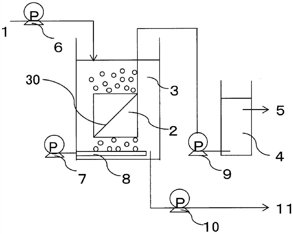
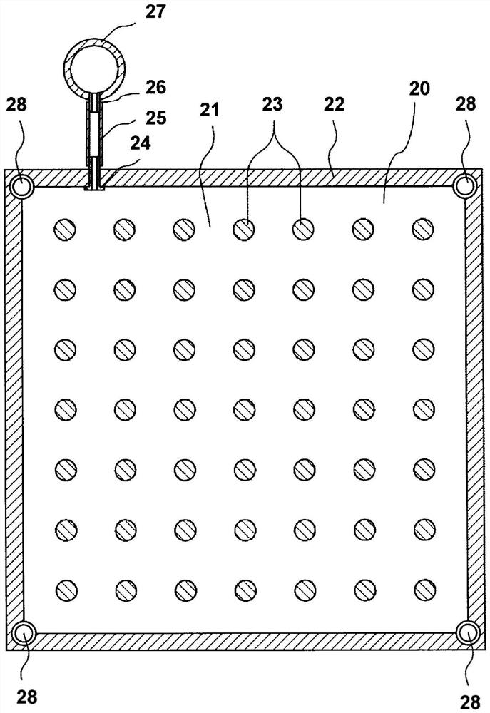
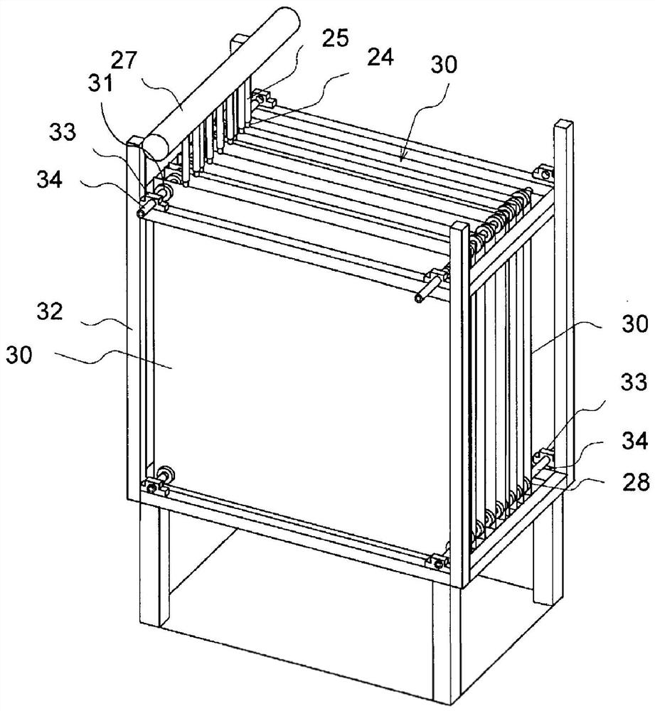
[0105] In an agricultural wastewater treatment facility, 50 units are installed at intervals of 7.5 mm between adjacent flat membrane elements using a gap-maintaining material made of ethylene-propylene rubber with a thickness of 7.5 mm. figure 2 The flexible flat membrane element shown (width 500mm×height 1000mm, thickness 3mm, effective membrane area is 1m 2 , polyvinylidene fluoride) impregnated membrane separation unit ( image 3 ),exist figure 1 The membrane separation activated sludge device shown (width 1.5m, depth 1m, height 3m, tank volume 4.5m 3 ) set a unit in the slot. A diffuser 8 for air supply was installed below the submerged membrane separation unit, and air was supplied to the diffuser 8 by the air supply device 7 at 330 NL / min / module. Using one unit of this device, the agricultural wastewater is used as the water to be treated, and the operation is performed for about 3 months while supplying air while filtering. Regarding the filtration flow rate, the ...

Embodiment 2

[0113] In the waste water treatment plant of polymer resin manufacturing engineering, 50 flexible membrane elements (width 500mm× Height 1000mm, thickness 3mm, effective membrane area 1m 2 , polyvinylidene fluoride) impregnated membrane separation unit ( image 3 ),exist figure 1 The membrane separation activated sludge device shown (width 1.5m, depth 1m, height 3m, tank volume 4.5m 3 ) set a unit in the slot. A diffuser 8 for air supply was installed below the submerged membrane separation unit, and air was supplied to the diffuser 8 by the air supply device 7 at 350 NL / min / module. Using one unit of this device, the waste water from the polymer resin manufacturing process was used as the water to be treated, and it was operated for about 3 months while supplying air while filtering. Regarding the filtration flow rate, the sludge is collected in advance, and it is set to 0.5m based on the results of the preliminary test 3 / m 2 / d.

[0114] The filtration pressure differ...

Embodiment 3

[0123]In the same polymer resin-based manufacturing engineering wastewater treatment plant as in Example 2, at a different time period (when the water temperature is low in winter) from the period of Example 2 (when the water temperature is high in summer), a machine with an impregnated water tank installed in the tank is used. The membrane separation activated sludge device of type membrane separation unit (device structure is identical with embodiment 2), carries out filtration operation. Here, in order to improve the filterability of the sludge, a cationic polymer coagulant was added based on the conditions determined by the preliminary test. 3 / m 2 / d, air supply 350NL / min / module) for operation.

[0124] The filtration pressure difference P1 at the initial stage of operation is 5kPa. After continuing the operation of filtering while supplying air for 3 months, the filter pressure difference reached 15 kPa set as the predetermined value P2, so cleaning was performed in th...


PUM


Abstract

A wastewater treatment method using a membrane separation activated sludge method, when using an immersion-type membrane separation unit loaded with multiple flexible membranes to perform filtration while supplying air, the filtration pressure of the membrane under the set filtration flow rate When the difference exceeds the predetermined value P2 relative to the filtration pressure difference P1 at the initial stage of operation, membrane filtration is performed with the air supply stopped until the filtration pressure difference P3 becomes P3≥P1+20[kPa], and then the filtration flow rate or filtration pressure is compared with one side. When the air supply is running while filtering, the air supply is smaller or becomes a negative value, and when the filter pressure difference P4 during filtering reaches P4≤P1+5[kPa], return to the filter while supplying air. run.

Description

technical field [0001] The invention relates to a wastewater treatment method for treating sewage, industrial wastewater and the like by adopting membrane separation activated sludge. Background technique [0002] The membrane separation activated sludge method used in the treatment of sewage and industrial wastewater is to carry out biological treatment in the biological reaction tank, and use the filter membrane immersed in the reaction tank to separate the activated sludge from solid and liquid to obtain clarification. water treatment methods. [0003] In the membrane separation activated sludge method, the membrane surface is always cleaned by the air supply from the bottom of the separation membrane unit, but if the operation continues for a long time, substances from the sludge that cannot be removed by the air supply alone may remain on the membrane. surface. Once they start to attach, they will reduce the effective surface area of ​​the membrane, and use it as a fo...

Claims


Application Information

Patent Timeline
Patent Type & Authority Patents(China)
IPC IPC(8): C02F3/12B01D63/08B01D65/02C02F1/44C02F11/147
CPCB01D65/02C02F3/1273C02F3/006C02F2209/03C02F2209/38C02F1/52C02F2303/16C02F3/20C02F3/101B01D65/08B01D2321/185B01D2315/06Y02W10/10B01D63/0821C02F11/147C02F3/208
Inventor 间谷圣子伊藤世人安东秀明
Owner TORAY IND INC
Learn More