A laser frequency shifter and a frequency shift method based on multi-frequency phase modulation

A laser frequency shifter and phase modulation technology, applied in the optical field, can solve the problems of complex equipment structure and low utilization rate of signal power, and achieve the effects of easy operation, high utilization rate of signal power and simple structure

Inactive Publication Date: 2018-12-21
ANHUI UNIVERSITY OF TECHNOLOGY AND SCIENCE
View PDF4 Cites 6 Cited by
  • Summary
  • Abstract
  • Description
  • Claims
  • Application Information

AI Technical Summary

Problems solved by technology

[0009] The present invention provides a laser frequency shifter and a frequency shift method based on multi-frequency phase modulation to solve the problems of low power utilization rate of signals in the prior art and complex equipment structure

Method used


Image

  • A laser frequency shifter and a frequency shift method based on multi-frequency phase modulation
  • A laser frequency shifter and a frequency shift method based on multi-frequency phase modulation
  • A laser frequency shifter and a frequency shift method based on multi-frequency phase modulation

Examples


specific Embodiment approach 1

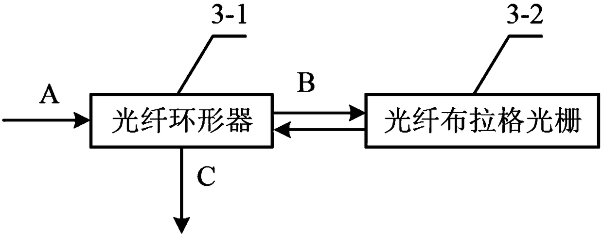
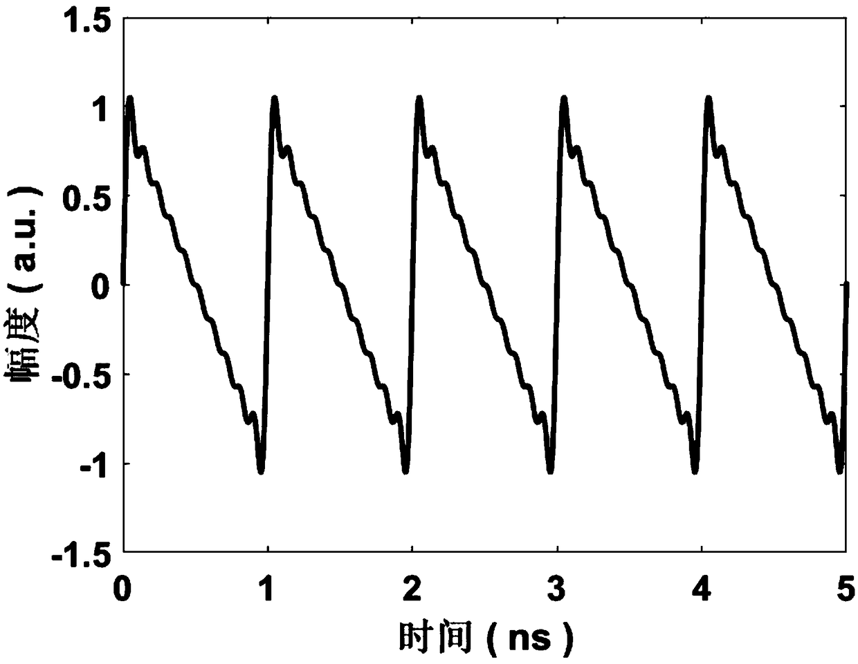
[0029] Specific implementation mode one: as figure 1 , figure 2 As shown, a laser frequency shifter based on multi-frequency phase modulation given in this embodiment includes a narrow linewidth laser source 1, an electro-optic modulator 2, a bandpass filter 3, a spectral measurement system 4, and an arbitrary waveform generator device 5 and radio frequency signal amplifier 6;

[0030] The output fiber of the laser source 1 of the narrow line width is connected to the pigtail of the input end of the electro-optic modulator 2, and the single-frequency signal output by the laser source 1 of the narrow line width is introduced into the electro-optic modulator 2;

[0031]The input end of the radio frequency signal amplifier 6 is connected to the arbitrary waveform generator 5, the output end of the radio frequency signal amplifier 6 is connected to the electro-optic modulator 2, and the output end of the electro-optic modulator 2 is connected to the optical fiber of the bandpass...

specific Embodiment approach 2

[0033] Embodiment 2: This embodiment is different from Embodiment 1 in that the spectral measurement system 4 is a spectrum analyzer, a spectrum analyzer or a scanning F-P interferometer.

[0034] Other steps and parameters are the same as those in the first embodiment.

specific Embodiment approach 3

[0035] Embodiment 3: This embodiment is different from Embodiment 1 or Embodiment 2 in that the narrow linewidth laser source 1 is provided by a narrow linewidth semiconductor laser. The wavelengths of the commonly used communication bands are 1550nm and 1310nm, and the wavelengths of the commonly used bands for laser medical treatment are 1064nm.

[0036] Other steps and parameters are the same as those in Embodiment 1 or 2.


PUM


Abstract

The invention provides a laser frequency shifter based on multi-frequency phase modulation and a frequency shift method, belonging to the optical technical field. The laser frequency shifter comprisesa laser source with narrow linewidth, an electro-optical modulator, a band-pass filter, a spectrum measuring system, an arbitrary waveform generator and a radio frequency signal amplifier.The methodof the invention comprises the following steps: firstly, the single-frequency signal output by a laser source with narrow linewidth is imported into an electro-optical modulator; then, the waveform ofthe multi-frequency modulated electric signal is obtained based on the reverse calculation of the spectrum analysis, and the arbitrary waveform generator is set to generate the corresponding multi-frequency modulated electric signal. At first, that modulate electric signal is amplified by a radio frequency signal amplify and transmitted to an electro-optical modulator; outputting the modulated optical signal to a band pass filter for frequency shifting; finally, the spectral structure is analyzed by the spectral measurement system. The invention solves the problems of low power utilization ratio of the prior art signal and complex equipment structure. The invention can be applied to wireless communication and optical fiber sensing.

Description

technical field [0001] The invention relates to a laser frequency shifter and a frequency shifting method, belonging to the field of optical technology. Background technique [0002] Distributed optical fiber sensors can measure the temperature, strain, micro-vibration and other parameters of each position of the optical fiber axis on the entire continuous optical fiber. Both occasion and scope have been raised to a new level. Distributed Brillouin fiber optic sensor is one of them, in which single-frequency pump light and signal light are incident into the fiber from both ends of the sensing fiber, and the frequency difference between signal light and pump light satisfies the Brillouin in the fiber When the frequency shifts, the stimulated Brillouin scattering (Stimulated Brillouin scattering, SBS) effect will occur and be amplified. The Brillouin frequency shift of each point in the optical fiber is directly related to the temperature and strain of the position. Therefo...

Claims


Application Information

Patent Timeline
Patent Type & Authority Applications(China)
IPC IPC(8): H04B10/572H04B10/50H04B10/556
Inventor 朱学华凌有铸代广珍王冠凌
Owner ANHUI UNIVERSITY OF TECHNOLOGY AND SCIENCE
Why Eureka
Try Eureka