A charging method and a charging device
A charging method and technology of a charging device, which are applied in the communication field and can solve problems such as long battery charging time
- Summary
- Abstract
- Description
- Claims
- Application Information
AI Technical Summary
Problems solved by technology
Method used
Image

Examples
Embodiment 1
[0034]The subject of execution of the charging method provided by the embodiment of the present invention may be the above-mentioned charging device, or may be a functional module and / or a functional entity in the charging device capable of implementing the charging method, which may be specifically determined according to actual usage requirements. The present invention Examples are not limited. The charging method provided by the embodiment of the present invention will be exemplarily described below by taking the charging device as an example as the execution subject.
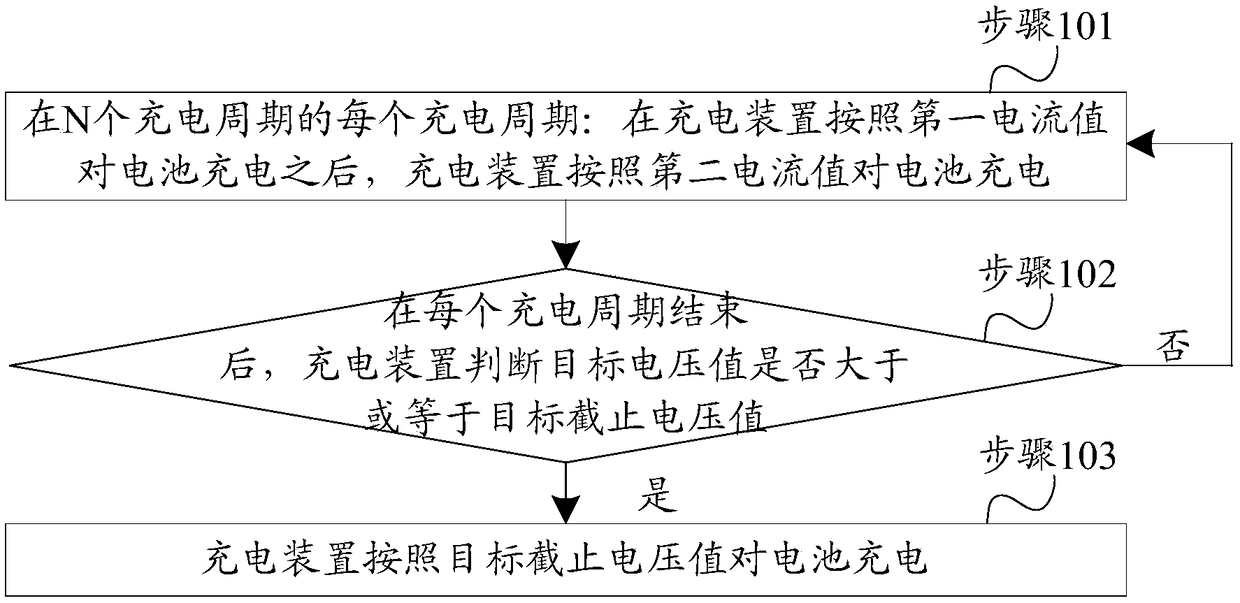
[0035] Such as figure 1 As shown, the embodiment of the present invention provides a charging method, and the charging method may include the following steps 101-103.
[0036] Step 101 , in each charging cycle of N charging cycles: after the charging device charges the battery according to the first current value, the charging device charges the battery according to the second current value.
[0037] Where...
Embodiment 2
[0098] Based on the charging method provided in the first embodiment above, two specific implementation manners are provided below.
[0099] Exemplarily, the battery in the embodiment of the present invention may include: an anode, a cathode, an electrolyte, a separator, and an aluminum-plastic film. Among them, the anode can be made of graphite with a ratio of 97.7%, styrene-butadiene rubber with a ratio of 1.0%, and methyl cellulose with a ratio of 1.3%. The cathode can be made of lithium cobaltate with a ratio of 97%, and a ratio of 1.6%. The polyvinylidene fluoride is mixed with 1.4% spandex, the electrolyte can be mixed with a certain proportion of organic solution, additives and electrolyte salt, and the diaphragm can be polyethylene film.
[0100] Implementation method one
[0101] When the ambient temperature of the battery is within the range of 15°C (Celsius) to 20°C, it is assumed that the rated power value (namely the rated capacity value) of the battery is Q nor...
Embodiment 3
[0143] Such as Figure 9 As shown, the embodiment of the present invention provides a charging device 900 . The charging device 900 may include a charging module 901 . Wherein, the charging module 901 is used for each charging cycle of N charging cycles: after the battery is charged according to the first current value, the battery is charged according to the second current value, the second current value is smaller than the first current value, N is a positive integer; and after each charging cycle ends, if the target voltage value is greater than or equal to the target cut-off voltage value, the battery is charged according to the target cut-off voltage value. Wherein, the target voltage value is a charging voltage value corresponding to the first current value, and the target cut-off voltage value is the first cut-off voltage value; or, the target voltage value is a charging voltage value corresponding to the second current value, and the target cut-off voltage value is A...
PUM
 Abstract
Description
Claims
Application Information
 - R&D
- Intellectual Property
- Life Sciences
- Materials
- Tech Scout
- Unparalleled Data Quality
- Higher Quality Content
- 60% Fewer Hallucinations
Browse by: Latest US Patents, China's latest patents, Technical Efficacy Thesaurus, Application Domain, Technology Topic, Popular Technical Reports.
© 2025 PatSnap. All rights reserved.Legal|Privacy policy|Modern Slavery Act Transparency Statement|Sitemap|About US| Contact US: help@patsnap.com