Passive cooling separation type heat pipe arrangement structure in spent fuel pool

A passive cooling, separate heat pipe technology, used in cooling devices, nuclear power generation, reactors, etc., can solve the problem that the heat exchange capacity of a single heat pipe cannot meet the requirements

Pending Publication Date: 2018-12-21
SHANGHAI NUCLEAR ENG RES & DESIGN INST CO LTD
View PDF0 Cites 0 Cited by
  • Summary
  • Abstract
  • Description
  • Claims
  • Application Information

AI Technical Summary

Problems solved by technology

[0004] Based on the heat load of the spent fuel pool, the heat exchange capacity of a single heat pipe cannot meet the requirements, and the entire heat pipe cooling system needs to include multiple evaporation tubes and multiple condenser tubes

Method used


Image

  • Passive cooling separation type heat pipe arrangement structure in spent fuel pool
  • Passive cooling separation type heat pipe arrangement structure in spent fuel pool
  • Passive cooling separation type heat pipe arrangement structure in spent fuel pool

Examples


Embodiment Construction

[0025] In order to make the above objects, features and advantages of the present invention more comprehensible, the present invention will be further described in detail below in conjunction with the accompanying drawings and specific embodiments.

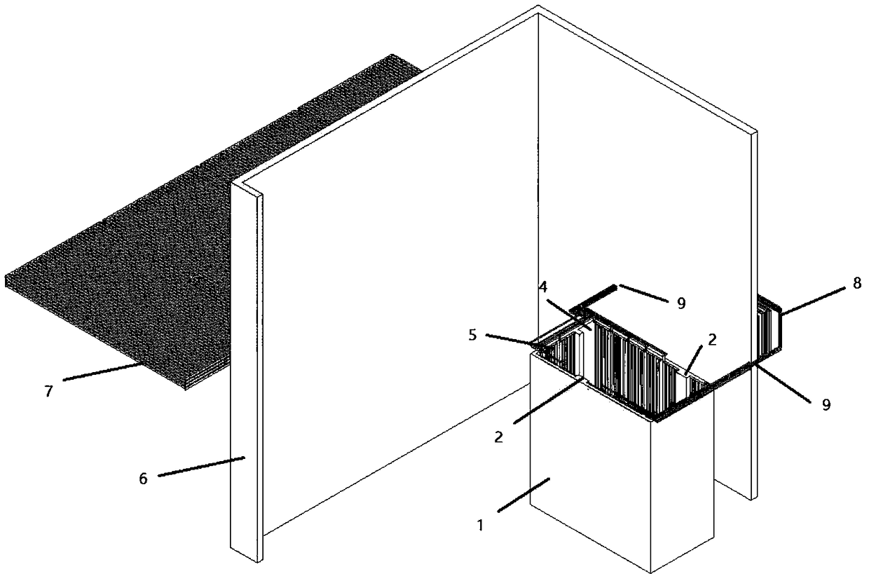
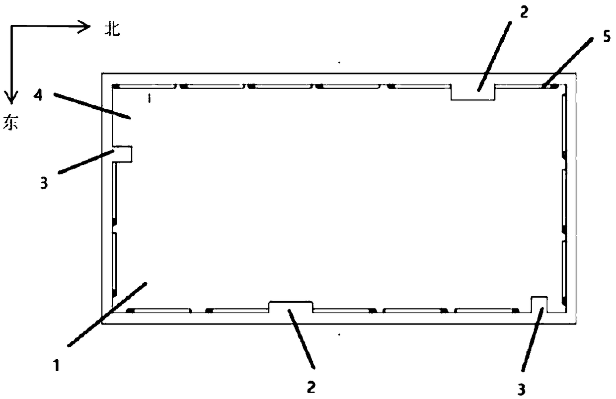
[0026] Such as figure 1 As shown, the passive cooling separated heat pipe arrangement structure in the spent fuel pool provided by an embodiment of the present invention, the separated heat pipe is mainly composed of the evaporation heat pipe 5, the condensation pipe 7 and the connecting pipe 8, and the evaporation heat pipe is arranged in the spent fuel pool 1. Below the level, it is necessary to avoid the area of ​​gate 2 and return pipe 3 at the same time. Considering that the heat load of the spent fuel pool is 5MW, the number of evaporation heat pipes required is 208, and the number of condenser pipes is 640.

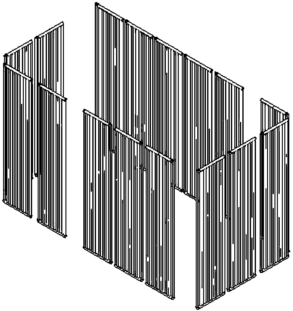
[0027] Such as figure 2 , image 3 As shown, the evaporating heat pipes are 13 assemblies arranged in a single r...


PUM


Abstract

The invention provides a passive cooling separation type heat pipe arrangement structure in a spent fuel pool. The passive cooling separation type heat pipe arrangement structure comprises an evaporation heat pipe, a condensing pipe and a connection pipe; the evaporation heat pipe is arranged in the spent fuel pool, and located below the liquid level in the spent fuel pool; the condensing pipe isarranged outside the spent fuel pool, and located above the roof of a radioactive waste workshop; and the connection pipe is arranged in the spent fuel pool, perpendicularly penetrates out of the spent fuel pool, and extends westwards along the radioactive waste workshop to penetrate out the radioactive waste workshop. The passive cooling separation type heat pipe arrangement structure in the spent fuel pool is characterized in that both the heat pipe evaporation section and the condensing section adopt assemblies, the number of the connection pipes is reduced so that the connection pipes canbe arranged in a simplified mode. The arrangement mode of the separation type heat pipe does not influence the number of the grillages stored in the spent fuel pool and the operation space, and support can be provided for design of a spent fuel pool cooling system.

Description

technical field [0001] The invention belongs to the field of cooling of spent fuel pools of nuclear power plants, and relates to the arrangement of large-scale separated heat pipes, in particular to an arrangement structure of passive cooling separated heat pipes in spent fuel pools. Background technique [0002] The AP1000 nuclear power plant introduced by my country and the CAP1400 and CAP1700 large-scale advanced pressurized water reactor nuclear power plants independently developed by China belong to the third-generation nuclear power technology, and adopt a large number of advanced passive safety technologies. [0003] The long-term cooling of the spent fuel pool is a problem of small temperature difference and large heat transfer. For this situation, a heat pipe heat exchanger is a viable option. In addition, AP1000 and subsequent CAP1400 and CAP1700 nuclear power plants and equipment are compactly arranged, and there is a certain distance between the spent fuel pool ...

Claims


Application Information

Patent Timeline
Patent Type & Authority Applications(China)
IPC IPC(8): G21C15/14
CPCG21C15/14Y02E30/30
Inventor 王芳叶成陈丽桂璐廷袁钢柴庆竹秦文松余欣匡以武罗云黄欣培韩菲王文
Owner SHANGHAI NUCLEAR ENG RES & DESIGN INST CO LTD
Why Eureka
Try Eureka