
Method and device for correcting differential rotary full tensor instrument

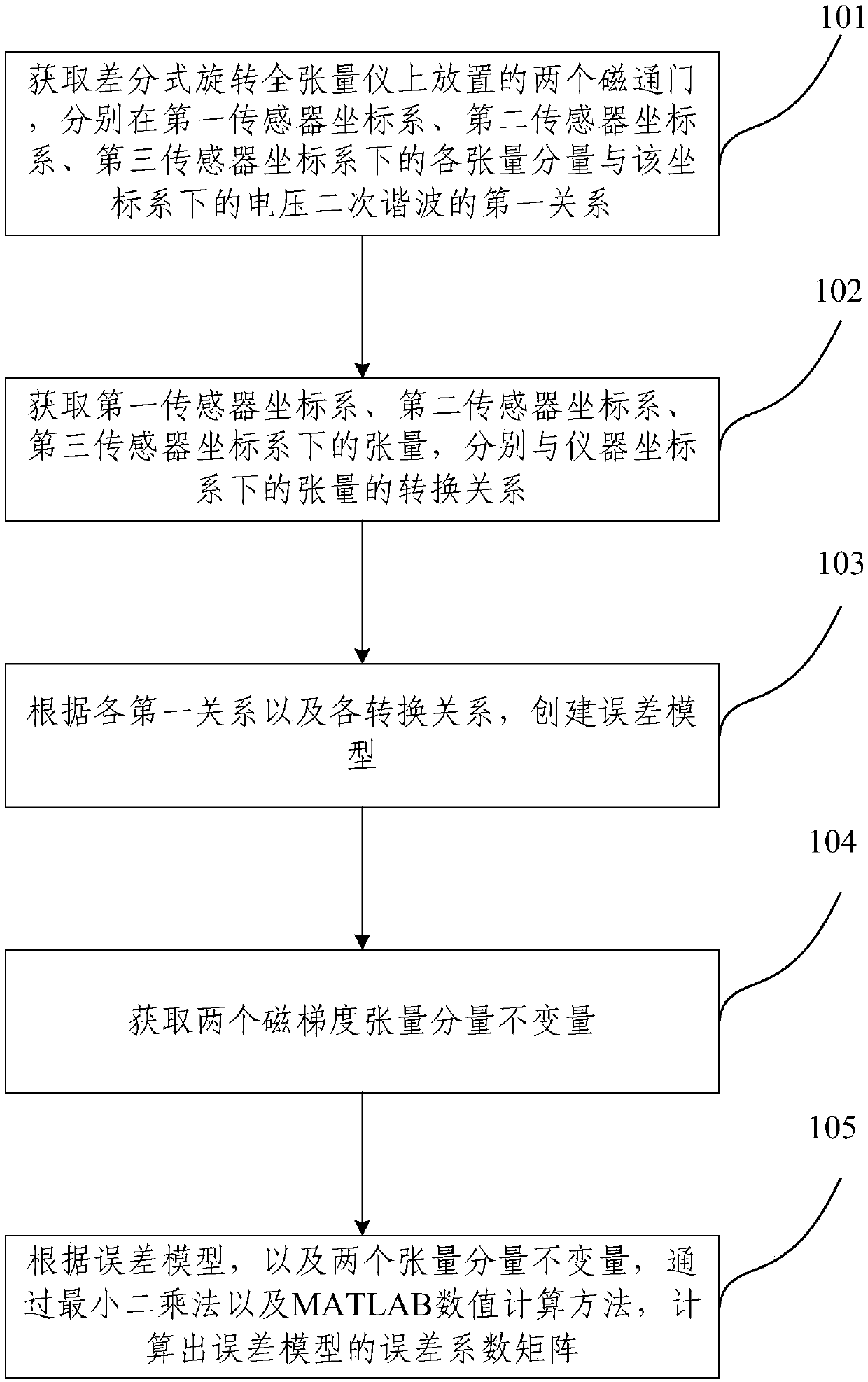
A calibration method and tensor technology, which can be applied to instruments, geophysical measurements, etc., and can solve the problems of error analysis and correction of differential rotating full tensor.

Active Publication Date: 2018-12-21
JILIN UNIV
View PDF4 Cites 10 Cited by
  • Summary
  • Abstract
  • Description
  • Claims
  • Application Information

AI Technical Summary

Problems solved by technology

[0006] The purpose of the embodiment of the present invention is to provide a method and device for correcting a differential rotating full tensor meter, which is used to solve the problem that there is no error analysis and correction method for the differential rotating full tensor meter in the prior art

Method used


Image

  • Method and device for correcting differential rotary full tensor instrument
  • Method and device for correcting differential rotary full tensor instrument
  • Method and device for correcting differential rotary full tensor instrument

Examples


Embodiment Construction

[0085] The implementation of the present invention will be illustrated by specific specific examples below, and those skilled in the art can easily understand other advantages and effects of the present invention from the contents disclosed in this specification.

[0086] It should be noted that the structures, proportions, sizes, etc. shown in the drawings attached to this specification are only used to match the content disclosed in the specification, for those who are familiar with this technology to understand and read, and are not used to limit the implementation of the present invention. Limiting conditions, so there is no technical substantive meaning, any modification of structure, change of proportional relationship or adjustment of size, without affecting the effect and purpose of the present invention, should still fall within the scope of the present invention. The disclosed technical content must be within the scope covered. At the same time, terms such as "upper"...


PUM


Abstract

The embodiment of the invention discloses a method and device for correcting a differential rotary full tensor instrument, and belongs to the technical field of correction of tensor instruments. According to the method for correcting the differential rotary full tensor instrument, according to the tensor transformation relation between a sensor coordinate system and an instrument coordinate system, an error model is established, a coefficient matrix in the error model is calculated, thus the corrected tensor value can be calculated through the error model, and the problem that an error analysis and correction method of a differential rotary full tensor instrument in the prior art does not exists is solved.

Description

technical field [0001] The invention relates to the technical field of tensor meter calibration, in particular to a differential rotary full tensor meter calibration method and device. Background technique [0002] In geophysical exploration, people use large-scale geomagnetic measurement and analysis of changes in geomagnetic declination to determine the distribution of magnetic iron deposits and various ores such as copper, nickel, chromium, and diamond. The current magnetic survey methods for land include airborne magnetic survey, surface magnetic survey and borehole magnetic survey. [0003] At present, the common magnetic measurements in wells are the total magnetic field and the three-component magnetic field measurement, but these two methods are greatly affected by the geomagnetic field and the casing in the borehole. In addition, the three-component magnetic field measurement is extremely sensitive to the direction. The magnetic gradient tensor has many advantages ...

Claims


Application Information

Patent Timeline
IPC IPC(8): G01V13/00
Inventor 随阳轶贺玮夏争辉刘世斌刘珂毕忠华
Owner JILIN UNIV
Learn More