
Reflective differential optical measuring system and reflective differential optical measuring method based on liquid crystal variable retarder

An optical measurement system and retarder technology, used in measurement devices, material analysis by optical means, instruments, etc., can solve the problems of low measurement speed of full-spectrum signals, low lateral spatial resolution, etc., to improve design efficiency and universal Good effect of sex and interchangeability

Inactive Publication Date: 2018-12-21
TIANJIN UNIV
View PDF4 Cites 10 Cited by
  • Summary
  • Abstract
  • Description
  • Claims
  • Application Information

AI Technical Summary

Problems solved by technology

[0003] The current reflective differential optical measurement system is mainly based on spectral signal measurement, the measurement speed of full-spectrum signal is low, and the error and noise introduced by mechanical vibration are unavoidable
In addition, the lateral spatial resolution of existing measurement methods is generally low

Method used


Image

  • Reflective differential optical measuring system and reflective differential optical measuring method based on liquid crystal variable retarder
  • Reflective differential optical measuring system and reflective differential optical measuring method based on liquid crystal variable retarder
  • Reflective differential optical measuring system and reflective differential optical measuring method based on liquid crystal variable retarder

Examples


Embodiment Construction

[0038] In order to make the object, technical solution and advantages of the present invention clearer, the present invention will be further described in detail below in conjunction with specific embodiments and with reference to the accompanying drawings.

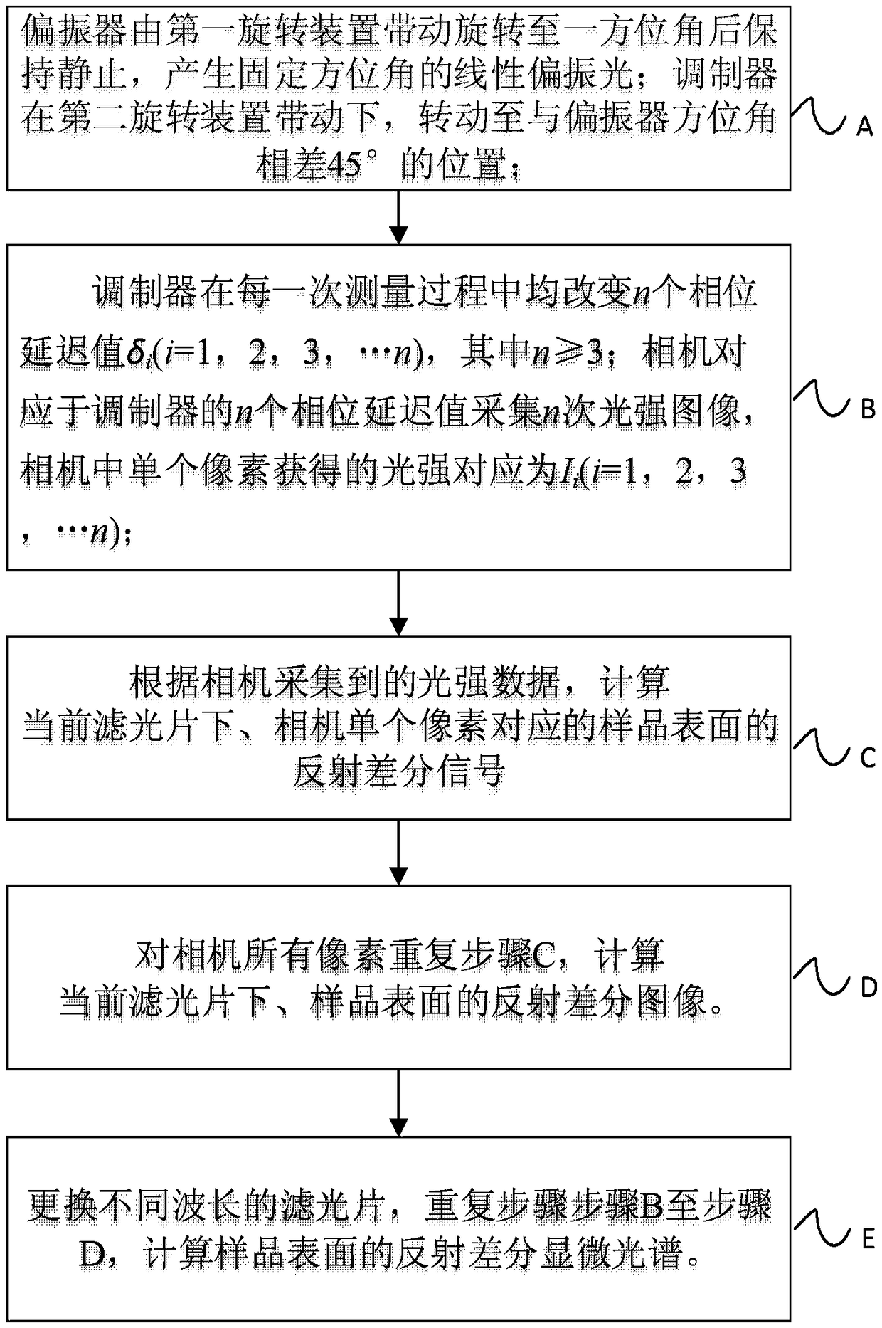
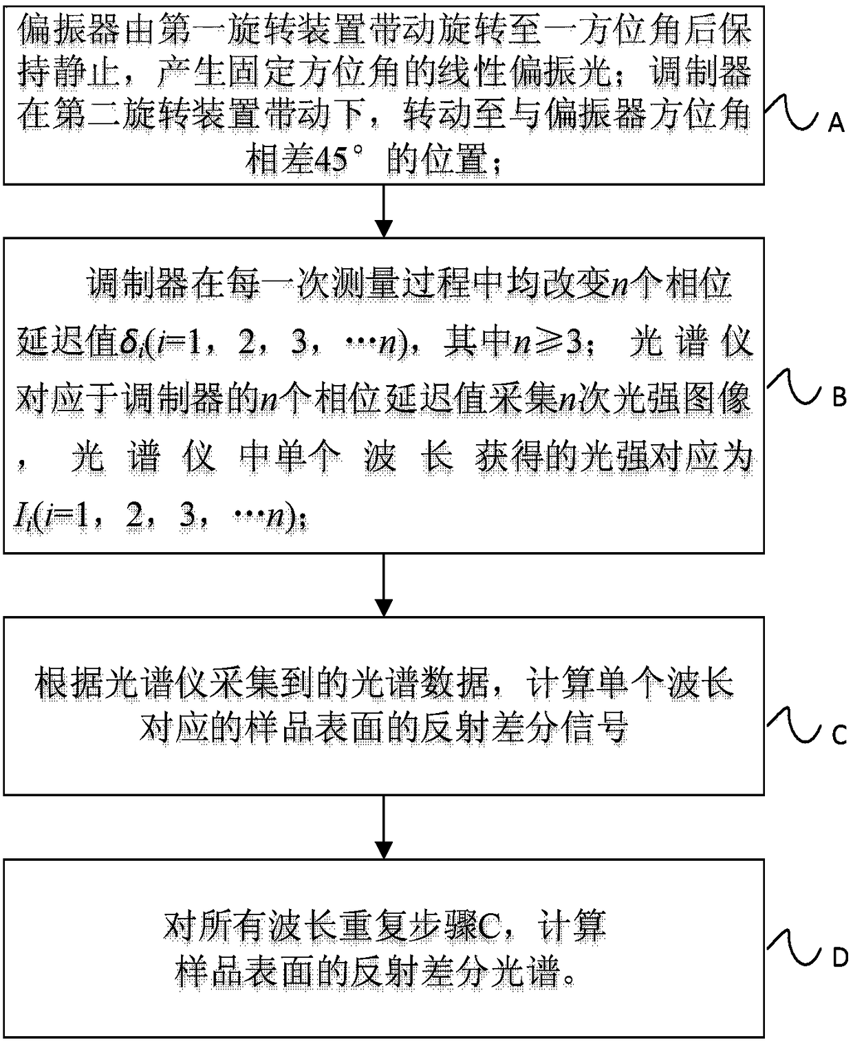
[0039] A reflective differential optical measurement system and method based on a liquid crystal variable retarder, the reflective differential optical measurement system based on a liquid crystal variable retarder includes: a light source module, used to generate non-polarized visible polychromatic parallel beams; The beam splitter reflects the light beam output by the light source module into the optical path, so that the outgoing light beam passing through the beam splitter continues to transmit into the optical path; the reflection difference module performs polarization state or phase delay modulation on the light beam outgoing from the first beam splitter; The objective lens is used to realize critical illumination a...


PUM

PropertyMeasurementUnit
diameteraaaaaaaaaa
diameteraaaaaaaaaa

Abstract

The invention discloses a reflective differential optical measuring system and reflective differential optical measuring method based on a liquid crystal variable retarder. The reflective differentialoptical measuring system comprises the following parts: a light source module, configured to generate a non-polarized visible complex color parallel beam; a first beam splitter, configured to reflectthe beam output by the light source module into an optical path to make the outgoing beam passing through the beam splitter continue to be transmitted into the optical path; a reflective difference module, configured to perform polarization or phase delay modulation on the beam emitted by the first beam splitter; a microscope objective, configured to achieve functions of critical illumination andoptical microscopy; a second beam splitter, configured to send the beam outputted by the first beam splitter into a corresponding signal acquisition module after transmission and reflection; and a signal acquisition module, configured to acquire light intensity signals. The reflective differential optical measuring system and reflective differential optical measuring method based on the liquid crystal variable retarder provided by the invention can realize microscopic spectrum measurement of optical reflection anisotropy of samples with no mechanical rotation during the measurement, and has the advantages such as simple structure, good stability and convenient adjustment.

Description

technical field [0001] The invention belongs to the field of optical characterization of ultra-thin films and the technical field of nanostructure testing, and in particular relates to a reflective differential optical measurement system and method based on a liquid crystal variable retarder. Background technique [0002] The optical characterization and testing methods of ultra-thin films and nanostructures play an important role in their process research and improvement. Among them, the reflection differential optical measurement technology measures the optical anisotropy caused by the reflection of the sample surface, and then conducts research and analysis on the morphology, physical and chemical properties of the sample. [0003] The current reflection differential optical measurement system is mainly based on spectral signal measurement, the measurement speed of full-spectrum signal is low, and the error and noise introduced by mechanical vibration are unavoidable. In...

Claims


Application Information

Patent Timeline
Patent Type & Authority Applications(China)
IPC IPC(8): G01N21/01G01N21/552
CPCG01N21/01G01N21/552
Inventor 胡春光霍树春沈万福李艳宁胡小唐
Owner TIANJIN UNIV
Learn More