
Compressor driver and compressor

A compressor and drive technology, applied in the field of compressors, can solve the problems of short stroke, large vibration of the crank-connecting rod mechanism, high center of gravity of the machine, etc., to reduce radial friction, improve dynamic transmission efficiency, and reduce energy consumption of the whole machine Effect

Active Publication Date: 2018-12-21
胡捷
View PDF20 Cites 0 Cited by
  • Summary
  • Abstract
  • Description
  • Claims
  • Application Information

AI Technical Summary

Problems solved by technology

[0003] The existing piston compressors have the following problems during use: According to the kinematic characteristics of the crank-connecting rod mechanism, during the movement of the piston, there is a large radial friction component between the piston and the cylinder wall, which will lead to Accelerate the wear of the piston and cylinder wall, resulting in increased leakage, low pressure and short service life; and there are problems of large vibration and noise during the operation of the crank connecting rod mechanism; the connection between the crank and connecting rod and the connecting rod There is relative rotation at the connection with the piston, which has the problems of high heat generation and low transmission efficiency; limited by the eccentricity of the crank, the existing piston compressors have short strokes, small compression ratios, large volumes, and high centers of gravity. stable problem

Method used


Image

  • Compressor driver and compressor
  • Compressor driver and compressor
  • Compressor driver and compressor

Examples


Embodiment Construction

[0026] The present invention will be further described below in conjunction with accompanying drawing.

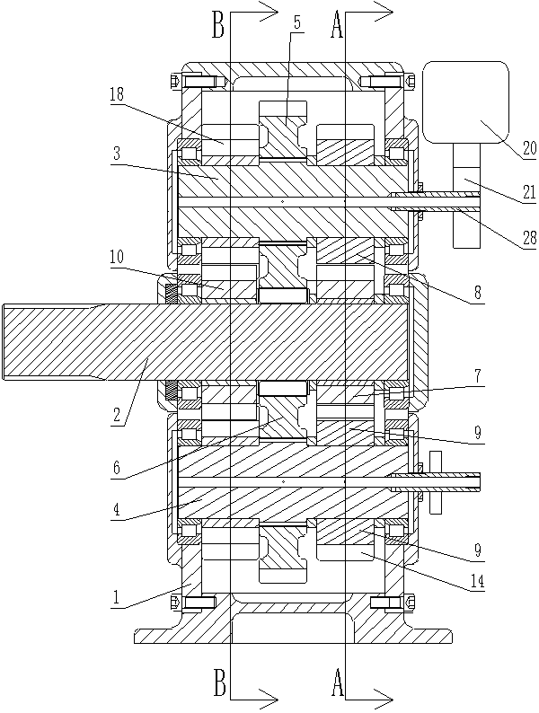
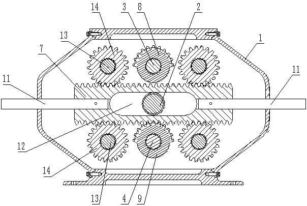
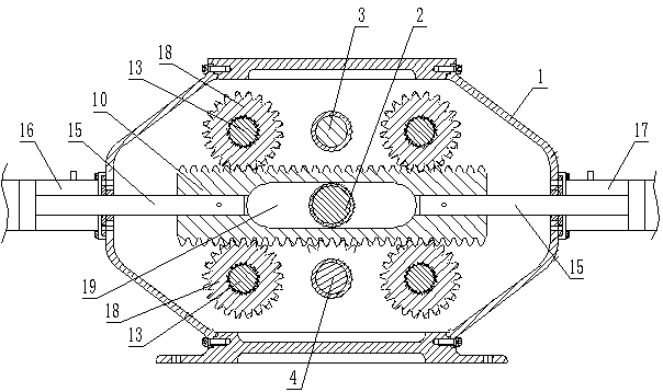
[0027] Such as Figure 1 to Figure 5 A compressor driver shown includes a housing 1 and an input shaft 2 rotatably mounted on the housing 1. The housing 1 is provided with an output rack 7 and a transmission member connected to the output rack 7. The input shaft 2 and the output rack 7 is provided with an incomplete rack and pinion mechanism for converting the rotary motion of the input shaft 2 into the reciprocating linear motion of the output rack 7, and the output rack 7 is fixedly connected with a The output shaft 11 extending in the direction of linear motion, the two ends of the output rack 7 are respectively provided with an output shaft 11, and the two output shafts 11 protrude outward from the housing 1, and also include a reciprocating linear motion that can drive the transmission part The hydraulic system can use the hydraulic system to provide thrust for the tr...


PUM


Abstract

The invention relates to a compressor driver and a compressor. The compressor drive comprises a case and an input shaft rotatably mounted on the case. An output rack and a transmission assembly whichis in transmission connection with the output rack are arranged in the case. An incomplete gear rack mechanism for converting the rotational motion of the input shaft to the reciprocating linear motion of the output rack is arranged between the input shaft and the output rack. Output shafts extending along the linear motion direction of the output rack are fixedly connected to the output rack. Thecompressor driver further comprises a hydraulic system capable of driving the transmission assembly to do reciprocating linear motion. According to the compressor driver and the compressor, the abrasion of the material is reduced, the dynamic transmission efficiency is improved, the compression ratio is improved, the driving speed is reduced, and the energy consumption of the whole machine is reduced; and the hydraulic thrust can be compensated according to the operating conditions.

Description

technical field [0001] The invention relates to a compressor, in particular to a compressor driver and a compressor. Background technique [0002] Existing piston compressors generally use a crank-link mechanism to convert the rotational motion of the motor into the reciprocating linear motion of the cylinder piston. For example: the Chinese patent application whose publication number is CN1624327A and the patent name is piston compressor, the Chinese patent application whose publication number is CN101796297A and the patent name is a compact dry-running piston compressor, and the publication number is CN205047394U and the patent name is The Chinese patent applications for reciprocating compressors and household appliances each disclose an existing piston compressor. [0003] The existing piston compressors have the following problems during use: According to the kinematic characteristics of the crank-connecting rod mechanism, during the movement of the piston, there is a l...

Claims


Application Information

Patent Timeline
Patent Type & Authority Applications(China)
IPC IPC(8): F16H19/04F15B1/02F15B11/16F04B35/04F04B35/00
CPCF04B35/008F04B35/04F15B1/02F15B11/16F16H19/043
Inventor 胡捷胡菱菱陈文艳
Owner 胡捷
Learn More