
A ball throwing machine system and its control method

A ball machine and control module technology, applied in the direction of program control, electrical program control, general control system, etc., can solve problems such as inability to obtain entertainment effects, inconvenience for players to use, increase in entertainment costs, etc., to prolong life, ensure stirring effect, The effect of reducing motor loss

Active Publication Date: 2020-08-11
朱江南
View PDF6 Cites 0 Cited by
  • Summary
  • Abstract
  • Description
  • Claims
  • Application Information

AI Technical Summary

Problems solved by technology

[0002] At present, ball throwing machines are generally used to assist athletes to practice, while ignoring their own entertainment functions. They cannot meet the needs of commercial entertainment and can store a large amount of balls at a time. When non-professional athletes perform entertainment exercises, if professional throwing If the ball throwing machine is not used, the proper entertainment effect cannot be obtained at all, and if the ball throwing machine is not suitable for practice, the participation of the training staff must be required, which increases the entertainment cost. Therefore, it is necessary to invent a ball throwing machine suitable for non-professional athletes. It is very necessary; so, once the existing ball throwing machine is directly used as practice for non-professional athletes, the existing ball throwing machine has less balls and complicated operation, which has caused great harm to the use of non-professional athletes. inconvenient

Method used


Image

  • A ball throwing machine system and its control method
  • A ball throwing machine system and its control method
  • A ball throwing machine system and its control method

Examples


specific Embodiment approach 1

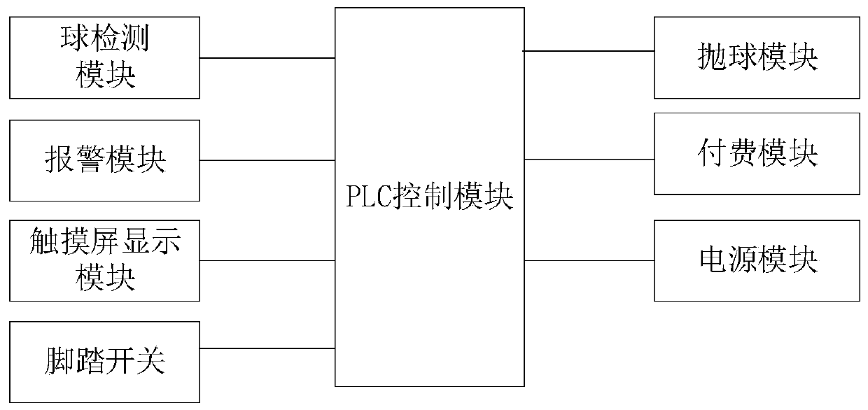
[0040] A ball throwing machine system such as Figure 1-6 As shown, it includes a touch screen display module, a PLC control module, a ball detection module, an alarm module, a ball throwing module, a payment module, a power supply module and a foot switch; the PLC control module is respectively connected to a touch screen display module, a ball detection module, and an alarm module , a throwing module, a payment module and a foot switch, the power module supplies power for a touch screen display module, a PLC control module, a ball detection module, an alarm module, a throwing module, a payment module and a foot switch;

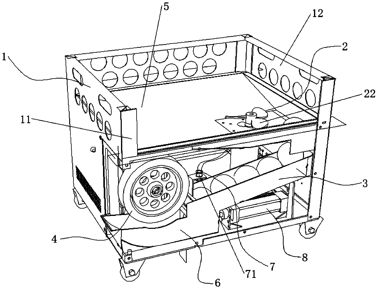
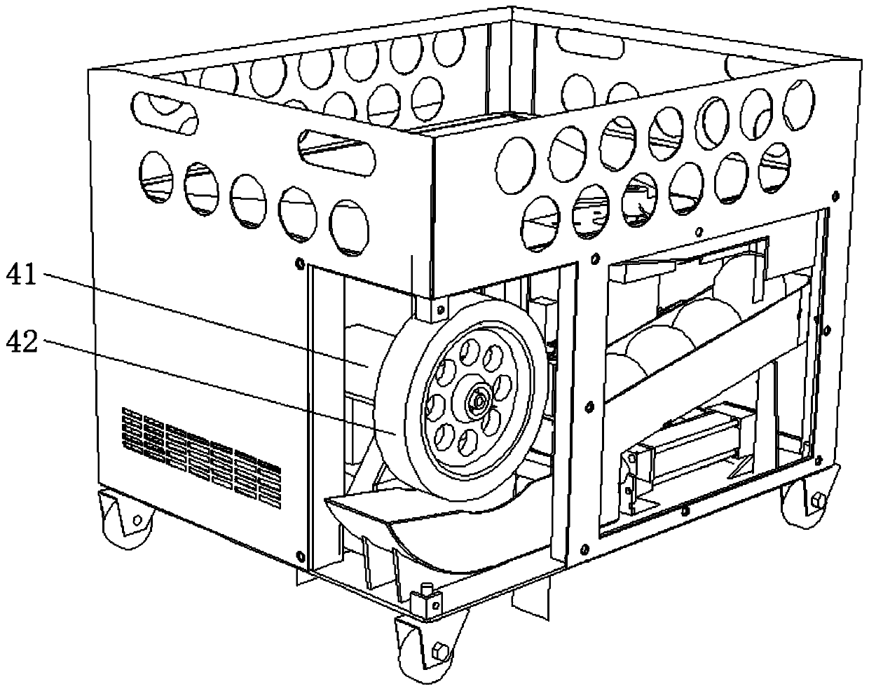
[0041] The ball throwing module includes an equipment frame 1, a mechanical stirring module 2, a transmission module 3, a serving module 4, a ball storage tank 5, a ball throwing arc groove 6, a pneumatic stirring module 7 and a cylinder pushing device 8; the equipment frame 1 The top is provided with a ball storage tank 5, and a group of mechanical stirring...

specific Embodiment approach 2

[0055] The difference from the first embodiment is that, if Figure 7 As shown, in this specific embodiment, the cylinder propulsion device 8 includes a set of drive motors 82, the main shaft of the drive motors 82 is fixedly connected with a set of drive screw screws 83, and a set of drive screw screws 83 is provided on the drive screw screws. The ball screw nut matched with the rod 83, the outer end sleeve of the ball screw nut is provided with a group of moving slides 85, and the moving slides are connected with a set of moving optical axes 84 through connecting pieces, and the moving optical axes are also provided with In a group of bearings, the bearings are set inside the equipment frame through a fixed frame, and the driving motor drives the screw to rotate, and then drives the ball screw nut and the moving slide to move linearly, and finally drives the moving optical axis to move in the bearing Inner rectilinear movement, fixing the push plate at the end of the moving ...

specific Embodiment approach 3

[0060] A control method based on the realization of the ball throwing machine system, such as Figure 8 shown, including the following steps:

[0061] Step a, turn on the power;

[0062] Step b, display the welcome interface and parameter settings through the touch screen display module, the parameters include the rotating speed of the ball, cylinder time and alarm time;

[0063] Step c, the touch screen display module transmits the information of parameter setting to the PLC control module, the PLC control module starts the PLC program operation, starts the ball detection module to collect and transmit the quantity of balls in the ball groove 31 in real time, and transmits the quantity information to the PLC control module, and the PLC The control module judges whether there is a sufficient number of balls, if the quantity is sufficient, proceed to step e, if the quantity is insufficient, proceed to step d;

[0064] Step d, the PLC control module controls the alarm module t...


PUM


Abstract

The invention provides a ball throwing machine system and a control method thereof, and belongs to the technical field of ball assistant training equipment. An existing ball throwing machine cannot accommodate many balls, and operation is complicated. The system includes a PLC control module, and the PLC control module is connected with a touch screen display module, a ball detection module, an alarm module, a ball throwing module, a payment module and a foot switch respectively. The power module supplies power to the touch screen display module, the PLC control module, the ball detection module, the alarm module, the ball throwing module, the payment module and the foot switch. The ball throwing module includes an equipment frame, the top of the equipment frame is provided with a ball storage groove, the ball storage groove is internally provided with a set of mechanical mixing module, the lower end of the ball storage groove is provided with a ball leakage opening, the ball leakage opening is connected with the ball feeding end of the transmission module, the ball outlet end of the transmission module is fixedly connected with a ball throwing arc groove, and the upper end of theball throwing arc groove is provided with a ball serving module. The ball outlet end of the transmission module is provided with an air blowing opening, and an air outlet hole is communicated with a pneumatic mixing module. Operation is simple, automatic ball leakage and warning of ball filling are achieved, and labor and material resources are saved.

Description

technical field [0001] The invention belongs to the technical field of ball game auxiliary training equipment, and in particular relates to a ball throwing machine system and a control method thereof. Background technique [0002] At present, ball throwing machines are generally used to assist athletes to practice, while ignoring their own entertainment functions. They cannot meet the needs of commercial entertainment and can store a large amount of balls at a time. When non-professional athletes perform entertainment exercises, if professional throwing If the ball throwing machine is not used, the proper entertainment effect cannot be obtained at all, and if the ball throwing machine is not suitable for practice, the participation of the training staff must be required, which increases the entertainment cost. Therefore, it is necessary to invent a ball throwing machine suitable for non-professional athletes. It is very necessary; so, once the existing ball throwing machine ...

Claims


Application Information

Patent Timeline
Patent Type & Authority Patents(China)
IPC IPC(8): A63B69/40G05B19/05
CPCA63B69/40G05B19/054G05B2219/1105
Inventor 朱江南周家为南春阳
Owner 朱江南
Learn More