Novel gas well mouth tube type circulating rotation flow dewatering device

A cyclone dehydration, gas well technology, applied in wellbore/well components, production fluid, combustible gas purification, etc., can solve the problems of large diameter of gas-liquid separator equipment, strict inlet flow rate requirements, and high liquid content in gas gathering pipelines. , to achieve the effect of improving the effective separation efficiency of gas-liquid two-phase, improving gas-liquid two-phase separation efficiency, and improving gas-liquid separation efficiency

Inactive Publication Date: 2018-12-21
BINZHOU UNIV
View PDF14 Cites 1 Cited by
  • Summary
  • Abstract
  • Description
  • Claims
  • Application Information

AI Technical Summary

Problems solved by technology

[0004] At present, there is no relevant gas-liquid separation equipment at the wellhead of the natural gas field in the gas field, resulting in a large amount of liquid in the gas-gathering pipeline and serious liquid accumulation in the pipeline. The situation is not ideal, the patented technology is mainly to improve the traditional process or equipment
Professor Sun Guogang of China University of Petroleum (Beijing) "A Multi-stage Cyclone Separator System for Staged Purification of Front-stage Separator Exhaust" (CN103056048B) provides a gas-solid, gas Liquid multi-purpose cyclone separator, which is characterized by multi-stage separation, but this invention has no industrial application; in order to enhance the target and high efficiency of the application of cyclone separator, a patent "a gas-liquid separation device" (CN2832267Y) was applied for and "A Gas-Liquid Separator" (CN100358638C), both of these two patents protect the same gas-liquid cyclone separation equipment, which is characterized by special gas-liquid separation, and high pressure resistance can achieve secondary cyclone separation, separation efficiency High, but the inlet flow rate is demanding, and it is mostly used in refineries with stable working conditions; Tianjin Xinyu Environmental Protection Technology Development Co., Ltd. Du Hongbin's invention patent "a gas-liquid cyclone separator" (CN103240191 B) completely draws on the original gas-solid The structural form of the separator is inevitably not adaptable in the actual application process; Dong Jinhua of Hebei University of Science and Technology's invention patent "a gas-liquid separator" (CN204280328 U) draws on the principle of gravity separation equipment, and the equipment itself is relatively large. It is difficult to adapt to the high pressure, intensive and high-efficiency requirements of the natural gas well site; the invention patent "high-efficiency gas-liquid cyclone separator" (CN103816724 A) of Sinopec Shanghai Engineering Co., Ltd. The problem of low use efficiency, this patent was proposed, which is characterized by being divided into inner and outer cylinders, and the inner cylinder contains fillers, resulting in a large pressure drop during the application of the equipment, and the need to clean the fillers regularly, the operation is complicated, and it is not conducive to unattended operation field application
The invention patent "High Efficiency Cyclone Separator for Gas Transmission Pipeline" (CN1133504C) developed a high-efficiency cyclone separator for gas transmission pipeline, but the separator still borrows the structure of the gas-solid separator, and the separation efficiency needs to be further improved

Method used


Image

  • Novel gas well mouth tube type circulating rotation flow dewatering device
  • Novel gas well mouth tube type circulating rotation flow dewatering device
  • Novel gas well mouth tube type circulating rotation flow dewatering device

Examples


Embodiment 1

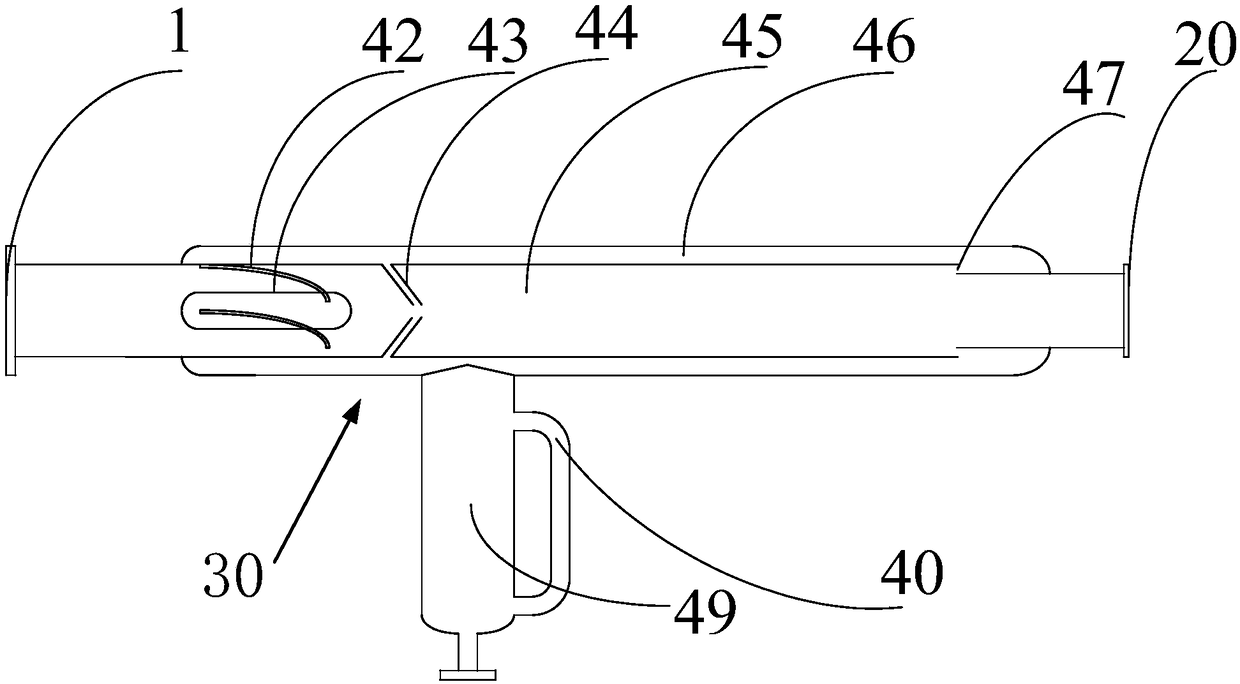
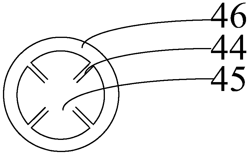
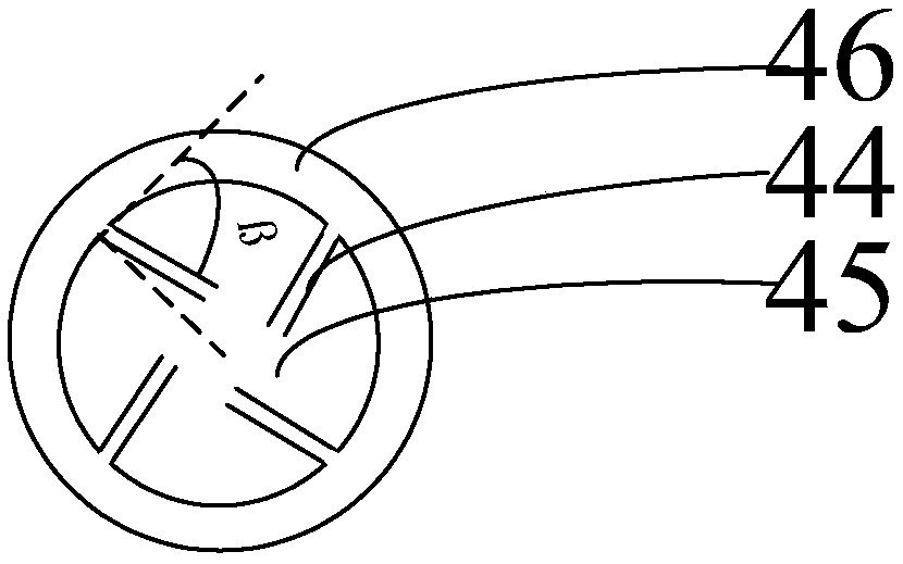
[0058] Embodiment one, such as Figures 1 to 4 As shown, the inner circulation cyclone dehydration assembly includes: a separation chamber 45 and an axial flow guide mechanism 42, and the axial flow guide mechanism 42 is attached to the axial flow guide shaft 43 on one side, and is sealingly connected with the attachment point of the axial flow guide shaft 43 , the other side of the axial guide mechanism 42 is attached to the inner wall of the separation chamber 45, and is in sealing connection with the attachment of the inner wall of the separation chamber 45. The end of the axial guide shaft 43 is provided with a hemispherical structure, and the hemispherical structure extends into the separation chamber. chamber 45, the outer layer of the separation chamber 45 is provided with a secondary separation diversion chamber 46; a first annular gap 47 is set between the separation chamber 45 and the secondary separation diversion chamber 46; the separation chamber 45 and the seconda...

Embodiment 2

[0064] Embodiment two: if Figures 5 to 11As shown, the internal circulation cyclone dehydration assembly includes: a primary internal circulation cyclone dehydration mechanism 50 and a secondary internal circulation cyclone dehydration mechanism 60; the input side of the primary internal circulation cyclone dehydration mechanism 50 and the cylindrical body 30 inlet Connected, the output side of the first-level internal circulation swirl dehydration mechanism 50 is connected with the input side of the second-level internal circulation swirl dehydration mechanism 60, and the output side of the second-level internal circulation swirl dehydration mechanism 60 is connected with the outlet 20 of the cylindrical body 30; The inner circulation cyclone dehydration mechanism 50 includes: a primary separation chamber 55 and a primary axial flow guide mechanism 52, the primary axial flow guide mechanism 52 is attached to the primary axial flow guide shaft 53 on one side, and is connected ...

Embodiment 3

[0076] Embodiment three: as Figures 12 to 16 As shown, the internal circulation cyclone dehydration assembly includes: four internal circulation cyclone dehydration mechanisms and a partition 18, the first end of the partition 18 and the inlet side of the cylindrical body 30 form the inlet chamber 2; the first end of the partition 18 The end and the outlet side of the cylindrical body 30 form an outlet chamber 9; the partition 18 evenly isolates the interior of the internal circulation cyclone dehydration assembly into four areas; each area is provided with an internal circulation cyclone dehydration mechanism 19.

[0077] In this embodiment, the internal circulation cyclone dehydration mechanism includes: a parallel secondary separation diversion chamber 6, a parallel separation chamber 7 and a parallel axial diversion mechanism 3; the parallel secondary separation diversion chamber 6 is attached to the cylindrical body 30 The inner wall is set, and the parallel secondary se...


PUM


Abstract

The invention provides a novel gas well mouth tube type circulating rotation flow dewatering device. The device has the advantages that axial diversion blades are utilized, so that the rotational floweffect is obtained, the device can be directly arranged on a gas production pipeline, the structure of a separator is compact, the equipment size is reduced, and the installation is convenient; underthe premise of not affecting the separation efficiency, the treatment capacity of the dewatering device is improved; a separation chamber and a secondary separation diversion chamber are utilized, thereby being capable of achieving the secondary circulating separation, and improving the gas-liquid two-phase separation efficiency; an inner circulating tube is utilized, thereby not occupying separation space of the separation chamber and secondary separation diversion chamber, and improving the gas-liquid two-phase effective separation efficiency; and an inner circulating device is utilized, thereby balancing the pressure difference between a liquid phase capturing device and the separation chamber, and being helpful for the separation chamber to improve the gas-liquid separation efficiency.

Description

technical field [0001] The invention relates to the field of natural gas exploitation, in particular to a novel gas well wellhead tubular circulating cyclone dehydration device. Background technique [0002] In the field of conventional onshore natural gas exploitation, based on considerations of production metering, safe transportation and efficient management, it is necessary to separate phases of gas-liquid mixtures upstream of natural gas production. Most of the separation devices used are horizontal and vertical settling tanks based on gravity separation technology. This type of device occupies a large area, has high engineering cost, long processing time and low production efficiency. According to local conditions, the gas-liquid separation device with cyclone separation technology as the key technology is widely used. According to different fluid flow directions, the separation device can be divided into tangential counter-flow type, axial counter-flow type and axial ...

Claims


Application Information

Patent Timeline
Patent Type & Authority Applications(China)
IPC IPC(8): E21B43/34C10K1/00B01D45/16
CPCB01D45/16C10K1/00E21B43/34
Inventor 封子艳崔铭伟封飞卞贺王成
Owner BINZHOU UNIV
Why Eureka
Try Eureka