
The switching control loop between the hydro-pneumatic suspension and the active suspension

A control loop and active suspension technology, which is applied to suspensions, elastic suspensions, vehicle components, etc., can solve the problems of non-adjustable accumulator pressure and difficulty in ensuring reliability

Active Publication Date: 2021-05-14
YANSHAN UNIV
View PDF6 Cites 0 Cited by
  • Summary
  • Abstract
  • Description
  • Claims
  • Application Information

AI Technical Summary

Problems solved by technology

[0004] The existing oil-gas suspension structure is mainly an interconnected oil-gas suspension structure, such as the publication number CN101618669A published in the Chinese patent on January 6, 2010. The invention name is "oil-air suspension control circuit, multi-axis vehicle oil-air suspension system and crane" Although it has many advantages, it also has some disadvantages: although the existing oil-pneumatic suspension can improve the ride comfort of the vehicle on uneven roads to a certain extent, the pressure of the accumulator cannot be adjusted when the vehicle is running. , the stiffness characteristics of the suspension can only be changed within a certain range, and its adjustment to complex road surfaces has great limitations; secondly, the interconnection of the oil-pneumatic suspension in a flexible state can improve the roll stiffness of the vehicle when it is running, but it is difficult for the vehicle to accelerate or The pitch adjustment during braking is helpless; in addition, this suspension system only has oil-air control mode, and there is no alternative solution, and its reliability is difficult to guarantee when the vehicle is driving for a long time

Method used


Image

  • The switching control loop between the hydro-pneumatic suspension and the active suspension
  • The switching control loop between the hydro-pneumatic suspension and the active suspension
  • The switching control loop between the hydro-pneumatic suspension and the active suspension

Examples


Embodiment Construction

[0023] The present invention will be described in further detail below in conjunction with the accompanying drawings and embodiments.

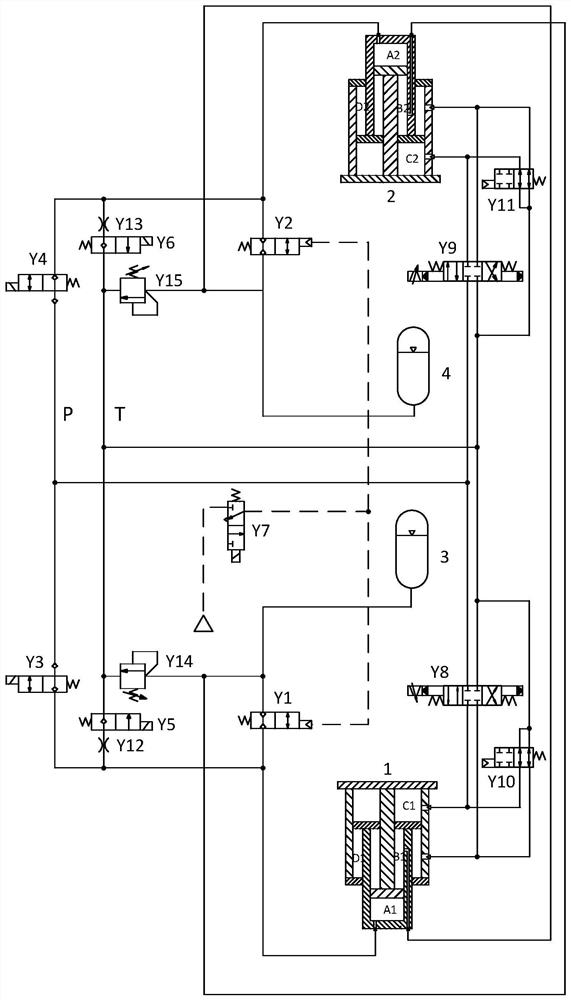
[0024] exist figure 1 In the schematic diagram of the oil-gas suspension and active suspension switching control circuit and the front view section of the suspension oil cylinder, the lower end cover 7 is fixedly connected to the lower end of the cylindrical outer cylinder 8, and the upper end of the outer cylinder is fixedly connected to the circular upper end cover 9 , oil ports are respectively provided on the wall of the outer cylinder near the upper and lower end caps. An inner cylinder 10 with an outer diameter corresponding to it is built in the center through hole of the upper end cover. The inner cylinder is a cylinder with a closed upper end. There are two oil ports on the wall of the inner cylinder, one of which is connected to the inner rodless cavity. A is connected, and the other oil port is connected with rod cavity B inside. ...


PUM


Abstract

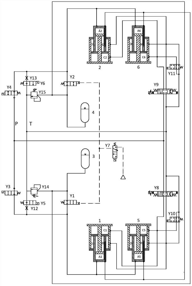
A oil-air suspension and active suspension switching control circuit and a suspension oil cylinder, first of all: the structure of the suspension oil cylinder is improved, that is, the outer cylinder wall of the suspension oil cylinder is provided with oil ports at the upper and lower sides, and the inner cylinder is built in the center through hole of the upper end cover. , the wall of the inner cylinder is provided with two oil ports respectively connected to the inner rodless cavity and the inner rod cavity, the end of the inner cylinder located in the outer cylinder is connected to the outer piston located in the outer cylinder, and the inner One end of the cylinder rod located in the inner cylinder is connected with the inner piston, and one end located in the outer cylinder is fixedly connected with the lower end cover. The present invention adds an active suspension control circuit to the existing interconnected oil-air suspension switching control circuit, which is based on the improved suspension oil cylinder, and adopts left and right servo valves and left and right oil-gas recovery control valves to cooperate with it. Through the active suspension control loop, three control modes of oil-air control, active control and rigidity control of the suspension system can be realized, and the three control modes can be switched mutually without affecting each other.

Description

technical field [0001] The invention relates to a vehicle suspension system. Background technique [0002] The suspension system is an important part of the vehicle chassis, which can not only support the frame, but also buffer the impact transmitted to the frame or body from uneven roads, and attenuate the vehicle vibration caused by the ground. The performance of the suspension system directly determines the ride comfort, handling stability and driving safety of the vehicle. [0003] Current vehicles, especially engineering vehicles, mostly adopt leaf spring suspension, oil-pneumatic suspension or air suspension. The stiffness characteristic of the leaf spring suspension is linear, and once the stiffness value is determined, it cannot be changed. When the road surface conditions change, it cannot meet the requirements of high driving comfort and handling stability. Oil-pneumatic suspension and air suspension have variable stiffness characteristics, which can improve the ...

Claims


Application Information

Patent Timeline
Patent Type & Authority Patents(China)
IPC IPC(8): B60G17/015B60G17/0165B60G17/019B60G17/052
CPCB60G17/015B60G17/0165B60G17/019B60G17/0525B60G2300/09B60G2500/10B60G2800/914
Inventor 赵丁选杜苗苗巩明德
Owner YANSHAN UNIV
Learn More