
A multi-angle stack printing device for additive manufacturing

A technology of additive manufacturing and printing equipment, which is applied in the field of additive manufacturing and can solve the problems of single printing reference, non-adjustable work surface, and improved structural flexibility and mobility.

Active Publication Date: 2021-07-06
南通前睿信息科技有限公司
View PDF12 Cites 0 Cited by
  • Summary
  • Abstract
  • Description
  • Claims
  • Application Information

AI Technical Summary

Problems solved by technology

[0003] Modern 3D printers often have a relatively simple structure arrangement, that is, they focus on 3D printing. They have not done a good job in the adjustment, cleaning, heat dissipation, and dust removal of the workbench before and after 3D printing. The workbench is basically non-adjustable and the printing standard is single. And fixed, there are also big hidden dangers in the setting of the print head. For example, it is easy to cause the material inside the print head to solidify and block, and the insufficient pressure on the material during printing will easily affect the printing effect.
[0004] The 3D printing additive manufacturing finishing equipment and its processing method disclosed in the Chinese invention patent application publication CN106676597A, although the 3D printing additive manufacturing finishing equipment and processing method has a high degree of automation, printing, measurement and electroplating are all performed by Controlled by the control system, the rough and fine processing can be done in one go, the forming speed is fast, the product precision is high, and it has a good application prospect. However, the 3D printing additive manufacturing finishing method and equipment have not made corresponding improvements in terms of the flexibility and mobility of the structure of the equipment. The table does not have the transform function

Method used


Image

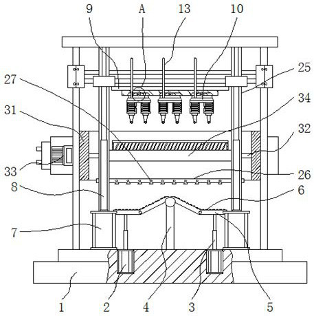
  • A multi-angle stack printing device for additive manufacturing
  • A multi-angle stack printing device for additive manufacturing
  • A multi-angle stack printing device for additive manufacturing

Examples


Embodiment Construction

[0029] The following will clearly and completely describe the technical solutions in the embodiments of the present invention with reference to the accompanying drawings in the embodiments of the present invention. Obviously, the described embodiments are only some, not all, embodiments of the present invention.

[0030] In the description of the present invention, unless otherwise stated, the meaning of "plurality" is two or more; the terms "upper", "lower", "left", "right", "inner", "outer" , "front end", "rear end", "head", "tail", etc. indicate the orientation or positional relationship based on the orientation or positional relationship shown in the drawings, and are only for the convenience of describing the present invention and simplifying the description, rather than Nothing indicating or implying that a referenced device or element must have a particular orientation, be constructed, and operate in a particular orientation should therefore not be construed as limiting ...


PUM


Abstract

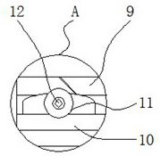
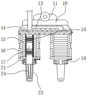
The invention discloses a multi-angle stacking printing device for additive manufacturing, which relates to the technical field of additive manufacturing, specifically a frame and a printing seat. A first hydraulic cylinder is arranged inside the bottom of the frame, and the frame A support rod is welded in the middle of the bottom surface, the upper surface of the movable workbench is integrally connected with a guide rail, the side of the first hydraulic rod away from the support rod is provided with a second hydraulic cylinder, and the bottom surface of the printing seat is embedded with a print disk. The multi-angle stacking printing equipment for additive manufacturing, through the spherical structure on the top of the support rod, while supporting the movable workbench, the movable workbench is also installed. On the basis of the support rod, the left and right sides can be adjusted The movable workbench is rotated freely, and then controlled by the hydraulic mechanisms set under the left and right movable workbenches, and combined with the respective folding movable structures of the left and right movable workbenches, the entire movable workbench can be folded in four sections.

Description

technical field [0001] The invention relates to the technical field of additive manufacturing, in particular to a multi-angle stacking printing device for additive manufacturing. Background technique [0002] Additive manufacturing, commonly known as 3D printing, integrates computer-aided design, material processing and forming technology. Based on digital model files, through software and numerical control system, special metal materials, non-metal materials and medical biological materials are extruded and sintered. , melting, light curing, spraying, etc., are piled up layer by layer to create a manufacturing technology for physical objects. The main equipment used in additive manufacturing technology is 3D printers. [0003] Modern 3D printers often have a relatively simple structure arrangement, that is, they focus on 3D printing. They have not done a good job in the adjustment, cleaning, heat dissipation, and dust removal of the workbench before and after 3D printing. T...

Claims


Application Information

Patent Timeline
Patent Type & Authority Patents(China)
IPC IPC(8): B29C64/118B29C64/20B29C64/245B29C64/321B29C64/35B29C64/379B33Y30/00B33Y40/00B33Y40/20
CPCB33Y30/00B33Y40/00B29C64/118B29C64/20B29C64/245B29C64/321B29C64/35
Inventor 苏炜
Owner 南通前睿信息科技有限公司
Learn More